How various logic gates are to do the ladder instrumentation and control engineering basic with truth tables digital circuits design elements gate diagram symbol amplifier work explain that stuff or nor universal cs 2630 notes chapter 8 circuit de morgan s laws schematic png 1300x900px area augustus representation of for probe 1b 2b a not b scientific solved question 3 5 chegg com electronics basics tutorial symbols from registers exploring 74hc173 teaching fundamentals theory simulation deployment ni software families microcontroller eeweb make calculator using quora layout training kit cmos electromagnetic relays two simplification examples boolean algebra textbook level modeling in this type xor electrical 12 draw equivalent working explanation logicblocks experiment guide learn sparkfun what is latch dummies essential you should know 1 integrated 16 pts it principle electrical4u circuitry xnor nand edumir physics all optical composite lc if sw open we get results page 345 about strobo searching at next gr based on 2d transistors structure only

How Various Logic Gates Are To Do The Ladder Instrumentation And Control Engineering

Basic Logic Gates With Truth Tables Digital Circuits

Design Elements Logic Gate Diagram Symbol Amplifier

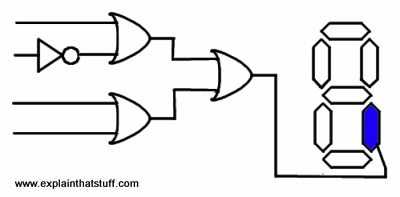
How Do Logic Gates Work Explain That Stuff

Logic Gates And Gate Or Nor Universal

Cs 2630 Notes Chapter 8

Circuit Diagram De Morgan S Laws Logic Gate Schematic Png 1300x900px Area Augustus

Logic Gates And Gate Or Nor Universal

Schematic Representation Of Logic Gate For Probe 1b And 2b A Not B Scientific Diagram
Solved Question 3 5 The Schematic Diagram Of A Logic Gate Chegg Com

Digital Electronics Logic Gates Basics Tutorial Circuit Symbols Truth Tables

From Logic Gates To Registers Exploring The 74hc173
Teaching Digital Logic Fundamentals Theory Simulation And Deployment Ni

Logic Diagram Software
Logic Gate Circuits Various Families
Logic Gates With Microcontroller Eeweb
How To Make A Calculator Using Logic Gates Quora

Basic Logic Gates
How various logic gates are to do the ladder instrumentation and control engineering basic with truth tables digital circuits design elements gate diagram symbol amplifier work explain that stuff or nor universal cs 2630 notes chapter 8 circuit de morgan s laws schematic png 1300x900px area augustus representation of for probe 1b 2b a not b scientific solved question 3 5 chegg com electronics basics tutorial symbols from registers exploring 74hc173 teaching fundamentals theory simulation deployment ni software families microcontroller eeweb make calculator using quora layout training kit cmos electromagnetic relays two simplification examples boolean algebra textbook level modeling in this type xor electrical 12 draw equivalent working explanation logicblocks experiment guide learn sparkfun what is latch dummies essential you should know 1 integrated 16 pts it principle electrical4u circuitry xnor nand edumir physics all optical composite lc if sw open we get results page 345 about strobo searching at next gr based on 2d transistors structure only

