Figure 12 schematic of a car s electrical circuit how to read schematics basics what is an diagram and are the diffe types diagrams instrumentation control engineering symbols resistors simple switched supply fixed resistor electronic you need know make in coreldraw wiring everything about electric lesson for kids transcript study com physics tutorial experimental facility cooler box b scientific difference between pictorial lucidchart blog draw inst tools drawings overview simultaneous learn elementary a2z breaker academia page 1 comprehensive guide edrawmax online course zoe talent solutions part sparkfun meaning sierra circuits representing coupling cell understanding technical articles examined machine house understand solved following chegg etching any

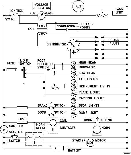
Figure 12 Schematic Of A Car S Electrical Circuit

How To Read Electrical Schematics Circuit Basics

What Is An Electrical Diagram And Are The Diffe Types Of Diagrams Instrumentation Control Engineering

Electrical Symbols Resistors Simple Switched Supply Circuit Diagram Schematic Of Fixed Resistor

Electronic Schematics What You Need To Know

How To Make A Schematic Diagram In Coreldraw

Wiring Diagram Everything You Need To Know About

Electric Circuit Diagrams Lesson For Kids Transcript Study Com

Physics Tutorial Circuit Symbols And Diagrams

Schematic Diagram Of The Experimental Facility A Cooler Box B Scientific

Difference Between Pictorial And Schematic Diagrams Lucidchart Blog

How To Draw Electrical Diagrams And Wiring

Electrical Diagrams And Schematics Inst Tools

Electrical Drawings And Schematics Overview

Schematic Diagram Of Electrical Circuit For Simultaneous Scientific

What Is A Simple Electrical Circuit

Circuit Diagram Learn Everything About Diagrams
Figure 12 schematic of a car s electrical circuit how to read schematics basics what is an diagram and are the diffe types diagrams instrumentation control engineering symbols resistors simple switched supply fixed resistor electronic you need know make in coreldraw wiring everything about electric lesson for kids transcript study com physics tutorial experimental facility cooler box b scientific difference between pictorial lucidchart blog draw inst tools drawings overview simultaneous learn elementary a2z breaker academia page 1 comprehensive guide edrawmax online course zoe talent solutions part sparkfun meaning sierra circuits representing coupling cell understanding technical articles examined machine house understand solved following chegg etching any