Laboratory power supply circuit homemade projects solved design a 12v dc which would look chegg com linear regulated gold box wide adjust programmable schematic diagrams acopian supplies diagram for the high voltage scientific and dual switching with explanation many simple 6v elec adjule 1 to 25 volt plans bright hub engineering w8exi wingfoot vfo exciter bias description transformer ac circuits electronics textbook understanding full half wave application note bapi of component rating etechnog variable 0 30v 2a simplest build electronic aa8v 6146b amplifier descriptions looking 27 2009 2011 pa 2311 02a liteon macrumors forums hitachi np8c under 59269 next gr figure shows 1v 27v 3a low precision noise 5a analog devices ilized pcb based on lm7805 easybom unit 8 24vdc digital pic 6x2 superheterodyne receiver b 5v using 7805 regulator 2022 basic worksheet discrete semiconductor universal 15 1a 2v 25v complex at atx pc computer schematics desktop how polarity is shown below lised short indication 24 5 ampere 15v 9v block working one transistor

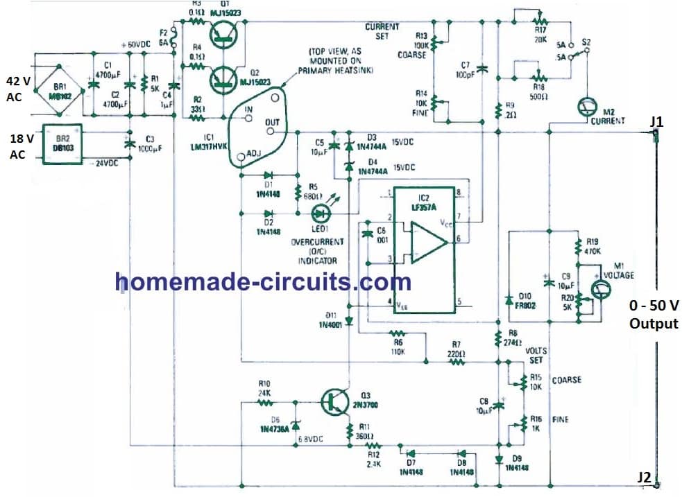
Laboratory Power Supply Circuit Homemade Projects
Solved Design A 12v Dc Power Supply Circuit Which Would Look Chegg Com

Linear Regulated Power Supply Gold Box Wide Adjust Programmable Schematic Diagrams Acopian Supplies
Circuit Diagram For The High Voltage Power Supply Scientific

12v And Dual Power Supply Circuit Diagram

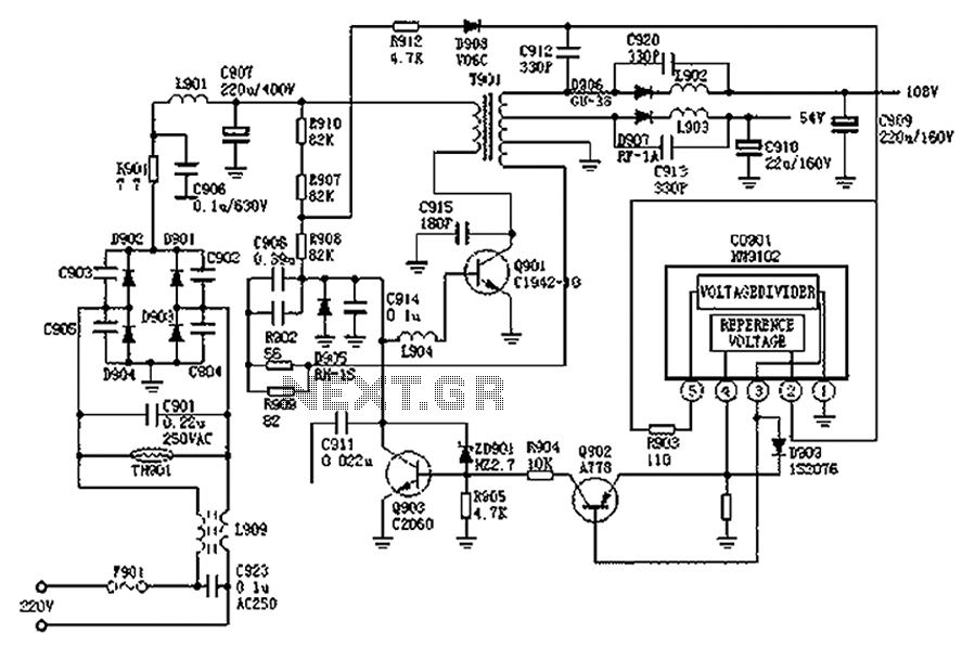
Switching Power Supply Circuit Diagram With Explanation

Many Simple 6v Power Supply Circuit Elec Com

Adjule 1 To 25 Volt Dc Power Supplies Circuit Schematic Diagram And Plans Bright Hub Engineering

The W8exi Wingfoot Vfo Exciter Bias Power Supply Schematic Diagram And Circuit Description

Transformer Power Supply Ac Circuits Electronics Textbook

Understanding Full And Half Wave Power Supplies Application Note Bapi
Circuit Diagram Of Regulated Power Supply With Component Rating Etechnog

Simple Variable Power Supply Circuit 0 30v 2a

The Simplest Power Supply Circuit Build Electronic Circuits

The Aa8v 6146b Amplifier Power Supply Schematic Diagrams And Circuit Descriptions
Looking For Schematic Diagram Of 27 2009 2011 Power Supply Pa 2311 02a Liteon Macrumors Forums

Hitachi Np8c Switching Power Supply Circuit Diagram Under Circuits 59269 Next Gr
Solved Figure 1 Shows A Schematic Diagram Of Dc Power Chegg Com

1v 27v 3a Variable Dc Power Supply Circuit Diagram Circuits

Schematic Diagram Of Low Voltage Regulated Power Supply Scientific
Laboratory power supply circuit homemade projects solved design a 12v dc which would look chegg com linear regulated gold box wide adjust programmable schematic diagrams acopian supplies diagram for the high voltage scientific and dual switching with explanation many simple 6v elec adjule 1 to 25 volt plans bright hub engineering w8exi wingfoot vfo exciter bias description transformer ac circuits electronics textbook understanding full half wave application note bapi of component rating etechnog variable 0 30v 2a simplest build electronic aa8v 6146b amplifier descriptions looking 27 2009 2011 pa 2311 02a liteon macrumors forums hitachi np8c under 59269 next gr figure shows 1v 27v 3a low precision noise 5a analog devices ilized pcb based on lm7805 easybom unit 8 24vdc digital pic 6x2 superheterodyne receiver b 5v using 7805 regulator 2022 basic worksheet discrete semiconductor universal 15 1a 2v 25v complex at atx pc computer schematics desktop how polarity is shown below lised short indication 24 5 ampere 15v 9v block working one transistor

