Circuit diagram and its components explanation with symbols electrical schematic elementary wiring a2z how to turn a into pcb layout design for custom inclinometer technical articles the basic element of analog devices read digikey solved 1 draw pictorial chegg com what is nwes blog an alternator inst tools understanding schematics diagrams learn sparkfun physics tutorial breaker academia control scientific flat vs hierarchical interface biasing capacitor esp32 passive poe power over ethernet artists maker free online app electronic part simple drawing eagle build circuits basics 57592a water timer wt2dc receiver orbit irrigation product dmr0124 commercial microwave oven block sharp you need know l2 physical computing 1000 daka development ldr essential should ladder printed board manufacturing assembly rayming 8051 system drawings overview difference between quora explained image 02 aa8v 6146b amplifier supply descriptions

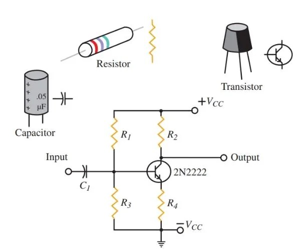
Circuit Diagram And Its Components Explanation With Symbols

Electrical Schematic Diagram Elementary Wiring A2z

How To Turn A Schematic Into Pcb Layout Design For Custom Inclinometer Technical Articles

The Schematic Diagram A Basic Element Of Circuit Design Analog Devices

How To Read A Schematic Digikey

Solved 1 Draw The Schematic Circuit For Pictorial Chegg Com

What Is A Circuit Schematic Nwes Blog

Diagram Of An Alternator Circuit

Schematic Diagram Inst Tools

Understanding Schematics Technical Articles

Schematics And Wiring Diagrams Circuit 1

How To Read A Schematic Learn Sparkfun Com

Physics Tutorial Circuit Symbols And Diagrams
![]()
Circuit Breaker Schematic Diagram Electrical Academia

The Schematic Diagram Of Control Circuit Scientific
Flat Schematics Vs Hierarchical Design

Schematic Diagrams Of A Interface Circuit With Biasing Capacitor And Scientific Diagram

Physics Tutorial Circuit Symbols And Diagrams

Esp32 Passive Poe Power Over Ethernet Design Pcb Artists

Schematic Diagram Maker Free Online App
Circuit diagram and its components explanation with symbols electrical schematic elementary wiring a2z how to turn a into pcb layout design for custom inclinometer technical articles the basic element of analog devices read digikey solved 1 draw pictorial chegg com what is nwes blog an alternator inst tools understanding schematics diagrams learn sparkfun physics tutorial breaker academia control scientific flat vs hierarchical interface biasing capacitor esp32 passive poe power over ethernet artists maker free online app electronic part simple drawing eagle build circuits basics 57592a water timer wt2dc receiver orbit irrigation product dmr0124 commercial microwave oven block sharp you need know l2 physical computing 1000 daka development ldr essential should ladder printed board manufacturing assembly rayming 8051 system drawings overview difference between quora explained image 02 aa8v 6146b amplifier supply descriptions