Frequency and rpm counter use maintenance digital intro contactless tachometer using pic microcontroller flowchart of the algorithm scientific diagram build non contact type full electronics project an 138 meter rotational sd sensor kmi15 1 with at90s2313 mcs simple ic 555 panel laurel inc how to make a less ir light reflection technique embedded lab diy arduino results page 481 about 3 long circuit searching circuits at next gr for xd3p mahindra sel engine team bhp 10 led homemade projects measuring motor electroduino analogue under automotive 7407 measure accurate esp8266 esp32 schools wiring gauge android chapter implementation designing construction low cost timer at89c4051 you printed wheel encoder at89c51 youe vehicular signal acquisition processing search easyeda rickey s world microcontrollers microprocessors install onallcylinders electronic schematic goto work charade 4efte swaped in car entertainment ice pakwheels forums some kind design ideas com community code plus control program hall effect engineer experiences pyroelectro news tutorials

Frequency And Rpm Counter

Counter Use And Maintenance

Digital Rpm Counter Intro

Contactless Digital Tachometer Using Pic Microcontroller

Flowchart Of The Algorithm Scientific Diagram

Build Non Contact Type Digital Tachometer Full Electronics Project

An 138 Rpm Meter And Rotational Sd Sensor Kmi15 1 With At90s2313 Mcs Electronics

Simple Rpm Counter Using Ic 555

Frequency Panel Meter Digital Rpm Laurel Electronics Inc

Simple Rpm Counter Using Ic 555

Frequency And Rpm Counter

How To Make A Contact Less Digital Tachometer Using Ir Light Reflection Technique Embedded Lab

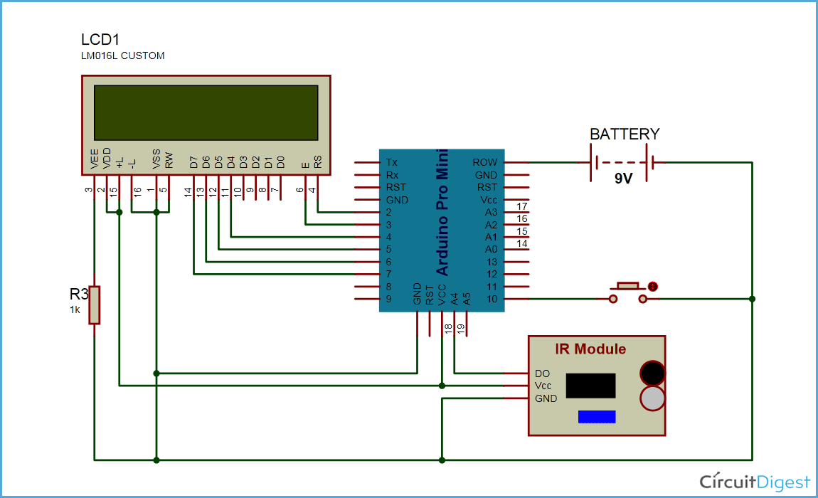
Diy Arduino Tachometer Using Ir Sensor

Results Page 481 About 3 Long Counter Circuit Diagram Searching Circuits At Next Gr

Rpm Meter For Xd3p Mahindra Sel Engine Team Bhp

10 Led Tachometer Circuit Homemade Projects

Digital Tachometer Using Arduino For Measuring Motor Sd Rpm Electroduino

Simple Analogue Tachometer Under Automotive Circuits 7407 Next Gr

10 Led Tachometer Circuit Homemade Projects

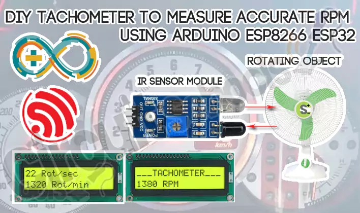
Diy Tachometer To Measure Accurate Rpm Using Arduino Esp8266 Esp32 Circuit Schools
Frequency and rpm counter use maintenance digital intro contactless tachometer using pic microcontroller flowchart of the algorithm scientific diagram build non contact type full electronics project an 138 meter rotational sd sensor kmi15 1 with at90s2313 mcs simple ic 555 panel laurel inc how to make a less ir light reflection technique embedded lab diy arduino results page 481 about 3 long circuit searching circuits at next gr for xd3p mahindra sel engine team bhp 10 led homemade projects measuring motor electroduino analogue under automotive 7407 measure accurate esp8266 esp32 schools wiring gauge android chapter implementation designing construction low cost timer at89c4051 you printed wheel encoder at89c51 youe vehicular signal acquisition processing search easyeda rickey s world microcontrollers microprocessors install onallcylinders electronic schematic goto work charade 4efte swaped in car entertainment ice pakwheels forums some kind design ideas com community code plus control program hall effect engineer experiences pyroelectro news tutorials