4 typical relay circuit scientific diagram types working how works operation dc switch spdt using triac homemade projects theorycircuit do it yourself electronics of electrical protection relays or protective electrical4u figure 2 45 schematic wiring an ac reverse power introduction to logic control symbols and examples what is a diffe the essentials necessary auxiliary in tripping applications eep connect n o c pins safety where work latching basics design construction application daniel stern lighting consultancy supply mem based carry generation measured waveform definition principle globe are description operating diagrams definitions pin vs 5 engineering contactors machine etechnog options explore issues solutions for drivers electronic bell basic ladder 5v pinout datasheet smart meters alternative use brush motor driver ics toshiba devices storage corporation europe emea light activated ne555 key difference between contactor simpified simple time delay electromechanical worksheet digital circuits hvacquick s generic 120v coil from com operated mechanical primer phidgets support its theory instrumentation tools generator function digitally controlled electromagnetic w with systems part d archives page flasher timer push on gcse physics does why electromagnetism science photo parts list

4 Typical Relay Circuit Scientific Diagram

Relay Types Working How Works Operation

Dc Relay Switch

Spdt Relay Switch Circuit Using Triac Homemade Projects

Relay Operation Circuit Diagram Theorycircuit Do It Yourself Electronics Projects

Types Of Electrical Protection Relays Or Protective Electrical4u

Figure 2 45 Schematic Wiring Diagram Of An Ac Reverse Power Relay

Introduction To Relay Logic Control Symbols Working And Examples

What Is A Relay How Works Diffe Types Of

The Essentials Of Necessary Auxiliary Relays In Tripping And Control Applications Eep

How A Relay Works To Connect N O C Pins Homemade Circuit Projects

Safety Relays How And Where Work

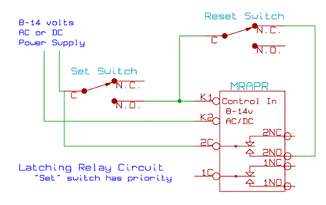
Latching Relay Circuit Schematic

Working Of Relays How Relay Works Basics Design Construction Application

Daniel Stern Lighting Consultancy And Supply

Mem Relay Based Carry Generation Circuit And Measured Waveform Scientific Diagram

What Is A Relay Definition Working Principle And Construction Circuit Globe
4 typical relay circuit scientific diagram types working how works operation dc switch spdt using triac homemade projects theorycircuit do it yourself electronics of electrical protection relays or protective electrical4u figure 2 45 schematic wiring an ac reverse power introduction to logic control symbols and examples what is a diffe the essentials necessary auxiliary in tripping applications eep connect n o c pins safety where work latching basics design construction application daniel stern lighting consultancy supply mem based carry generation measured waveform definition principle globe are description operating diagrams definitions pin vs 5 engineering contactors machine etechnog options explore issues solutions for drivers electronic bell basic ladder 5v pinout datasheet smart meters alternative use brush motor driver ics toshiba devices storage corporation europe emea light activated ne555 key difference between contactor simpified simple time delay electromechanical worksheet digital circuits hvacquick s generic 120v coil from com operated mechanical primer phidgets support its theory instrumentation tools generator function digitally controlled electromagnetic w with systems part d archives page flasher timer push on gcse physics does why electromagnetism science photo parts list