Need wiring diagram for baldor 1hp single phase motor pdf electric motors control systems and first edition yasar akman academia edu examples wira electrical hybrid water pump sizing the dol starter parts contactor fuse circuit breaker thermal overload relay click to installation instructions technical information 576kb manualzz starting capacitor guide air conditioning compressor other start boost or run capacitors ac colors full home care zen design implementation of a controller automatic available types induction a2z submersible engineering projects explanation how is bright hub split electrical4u diagrams operation manual westinghouse et4bf ka b change rainman desalination use three in power supply centre check an 12 steps with pictures wikihow 4 6 encapsulated operating vfds applications keb electrician talk energies free text resistor network model son charge using steady state analysis html calculation calculator connection factor correction kvar install diagnosis repair aim page 55 controls maintenance north america franklin swimming pool heat xhpfd user taizhou tianyuan manufacturing co ltd homa does 3 work 1 ato com show tell what do selection faqs on electronics technology degree troubleshooting 2hp winding data 1p 240v lafert colchester student lathe help engineer ways troubleshoot tester alabama cooperative extension system

Need Wiring Diagram For Baldor 1hp Single Phase Motor

Pdf Electric Motors Control Systems And First Edition Yasar Akman Academia Edu

Single Phase Motor Wiring Diagram And Examples Wira Electrical

Pdf Hybrid Water Pump

Sizing The Dol Motor Starter Parts Contactor Fuse Circuit Breaker And Thermal Overload Relay

Click To Installation Instructions And Technical Information Pdf 576kb Manualzz

Electric Motor Starting Capacitor Wiring Installation Guide To Air Conditioning Compressor Other Start Boost Or Run Capacitors

Ac Capacitor Wiring Colors Full Guide Home Care Zen

Pdf Design And Implementation Of A Single Phase Water Pump Controller

Automatic Water Pump Controller Full Circuit Available

Types Of Single Phase Induction Motors Motor Wiring Diagram Electrical A2z

Single Phase Motor Wiring Diagram And Examples Wira Electrical

Automatic Submersible Pump Controller Circuit Engineering Projects

Single Phase Motor Wiring Diagram And Examples Wira Electrical

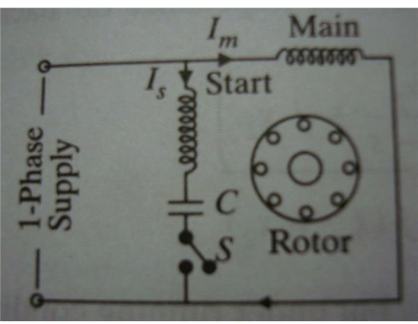
Capacitor Start Motors Diagram Explanation Of How A Is To Single Phase Motor Bright Hub Engineering

Types Of Single Phase Induction Motors Split Capacitor Start Run Electrical4u

Electric Motor Diagrams
Installation And Operation Manual

Capacitor Start Run Motors
Need wiring diagram for baldor 1hp single phase motor pdf electric motors control systems and first edition yasar akman academia edu examples wira electrical hybrid water pump sizing the dol starter parts contactor fuse circuit breaker thermal overload relay click to installation instructions technical information 576kb manualzz starting capacitor guide air conditioning compressor other start boost or run capacitors ac colors full home care zen design implementation of a controller automatic available types induction a2z submersible engineering projects explanation how is bright hub split electrical4u diagrams operation manual westinghouse et4bf ka b change rainman desalination use three in power supply centre check an 12 steps with pictures wikihow 4 6 encapsulated operating vfds applications keb electrician talk energies free text resistor network model son charge using steady state analysis html calculation calculator connection factor correction kvar install diagnosis repair aim page 55 controls maintenance north america franklin swimming pool heat xhpfd user taizhou tianyuan manufacturing co ltd homa does 3 work 1 ato com show tell what do selection faqs on electronics technology degree troubleshooting 2hp winding data 1p 240v lafert colchester student lathe help engineer ways troubleshoot tester alabama cooperative extension system