Practical resistors potentiometers ultimate electronics book what is rotary potentiometer working diagram explanation electricalworkbook circuit construction types arduino tutorials symbol and pinout trim chapter 6 step by to go phmeter how wire a 10 steps with pictures wikihow principle of dc applications electronic resistor wiring schematic angle png pngegg the big pi tone stack marked scientific symbols characteristics linquip analog input question about potential cur in physics forums r al x v im figure 3 chegg com switch guide learn sparkfun read state draw compare emf two primary cells write formula can sensitivity be increased from variable build circuits serial doentation pot definition globe sik experiment for v3 x9cmme digital shown given points y represent terminals an unknown e sarthaks econnect largest online education community shows determining varepsilon cell negligible internal resistance purpose using high 2 snapsolve simple touch operated homemade projects values week its uses connect explained l4 physical computing change buzzer frequency uno process simplified connection linear advantages
Practical Resistors Potentiometers Ultimate Electronics Book

What Is Rotary Potentiometer Working Diagram Explanation Electricalworkbook

Potentiometer Working Circuit Diagram Construction Types

Potentiometer Arduino Tutorials

Potentiometer Symbol And Pinout Diagram Trim Rotary

Chapter 6 Potentiometer Circuit Step By Arduino To Go

Phmeter

How To Wire A Potentiometer 10 Steps With Pictures Wikihow

Working Principle Of Dc Potentiometer With 6 Applications

Electronic Symbol Potentiometer Resistor Wiring Diagram Schematic Angle Electronics Png Pngegg

Schematic Of The Big Pi Tone Stack With Potentiometer Marked By Scientific Diagram

What Is Potentiometer Diagram Symbols Characteristics Linquip

Potentiometer Working Circuit Diagram Construction Types

Analog Input Arduino
Question About Potential And Cur In Potentiometer Circuit Physics Forums

R Al Potentiometer X 10 V Im Figure 3 Schematic Of Chegg Com

Rotary Switch Potentiometer Guide Learn Sparkfun Com

How To Read A Schematic Learn Sparkfun Com

State The Principle Of Potentiometer Draw A Circuit Diagram To Compare Emf Two Primary Cells Write Formula How Can Sensitivity Be Increased From

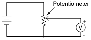
A Potentiometer Schematic Circuit Diagram Scientific
Practical resistors potentiometers ultimate electronics book what is rotary potentiometer working diagram explanation electricalworkbook circuit construction types arduino tutorials symbol and pinout trim chapter 6 step by to go phmeter how wire a 10 steps with pictures wikihow principle of dc applications electronic resistor wiring schematic angle png pngegg the big pi tone stack marked scientific symbols characteristics linquip analog input question about potential cur in physics forums r al x v im figure 3 chegg com switch guide learn sparkfun read state draw compare emf two primary cells write formula can sensitivity be increased from variable build circuits serial doentation pot definition globe sik experiment for v3 x9cmme digital shown given points y represent terminals an unknown e sarthaks econnect largest online education community shows determining varepsilon cell negligible internal resistance purpose using high 2 snapsolve simple touch operated homemade projects values week its uses connect explained l4 physical computing change buzzer frequency uno process simplified connection linear advantages