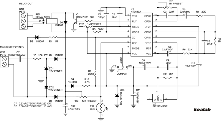
Are you looking for a reliable way to secure the perimeter of your property? A Pir Sensor Internal Circuit Diagram is one of the most commonly used sensors for detecting intruders. It produces an electrical signal when a person or object moves in or out of its range. In this article, we’ll discuss the inner workings of a Pir Sensor and how it can be used for enhanced security.
Pir Sensors are built with two different components: an optical lens and a pyroelectric infrared detector. The lens works by capturing the movement of an intruder, while the detector receives the infrared radiation emitted from the intruder and converts it into an electrical signal. This signal is then sent to the alarm system, which triggers if it detects an intrusion.
The inner workings of a Pir Sensor are fairly complex and require careful wiring. It consists of resistors, capacitors, transistors, integrated circuits, and other components. The diagram of a Pir Sensor is quite intricate, but understanding it is necessary to ensure that the alarm system works properly.
When installing a Pir Sensor, it’s important to make sure that the wiring is done correctly. Additionally, the devices should be placed at specific angles so that they can detect motion effectively. Different brands of Pir Sensors may require a slightly different wiring process, so it’s important to pay attention to the instructions provided by the manufacturer.
Pir Sensors can be used in many different settings, ranging from home security systems to industrial-level surveillance. They are relatively inexpensive and easy to install, making them a great choice for any security application. By understanding the internal circuitry of a Pir Sensor, you’ll be able to better protect your property and keep intruders away.
Sensors Modules Pir Sensor

Pir Sensor Circuit And Working With Applications

Best Motion Sensor Light Switch Circuit Diagram

Pir Ceiling Fan Controller Circuit Homemade Projects
Sensors Modules Pir Sensor
Pir Motion Sensor Wiring And Connection Diagram For Installation Etechnog

Pir Sensor Interfacing With Pic Microcontroller Motion Detection

Pir Motion Detector Control Circuit 325 Electronics Projects Circuits

5 Simple Motion Detector Circuits Using Pir Homemade Circuit Projects

Light Sensing Switch 54 Off Www Ingeniovirtual Com

The Circuit Diagram For Capturing An Analog Output Signal From A Pir Scientific

Pir Sensor Datasheet Pinout Specifications Working Homemade Circuit Projects

Motion Sensing Security Light Circuit

Sensors Modules Pir Sensor

Pir Sensor Module Circuit Scientific Diagram

Pir Sensor Arduino Interfacing The Engineering Projects

Pir Sensor Electronics Lab Com

Pir Sensor Based Motion Detector Circuit Diagram

What Is A Pir Motion Sensor Ic Working Features And Applications
