Do you ever feel like your home needs a little extra protection? With advances in technology, you can now enjoy the peace of mind that comes with knowing that you are safe and secure. One way to help achieve this is by using a PIR (Passive Infrared) Sensor Circuit Diagram.
A PIR Sensor Circuit Diagram is an electronic device which is used to detect the presence or movement of people or objects within its range. It responds to changes in infrared radiation that occur when someone moves near it, and can be used to trigger alarms, lights, etc. This makes it ideal for home security, providing a layer of protection against would-be intruders.
But how exactly does it work? Well, the PIR sensor is made up of two components, an infrared transmitting element and an infrared receiving element. The transmitting element emits infrared waves which spread out in all directions and eventually reach the receiving element. When movement or heat is detected near the PIR sensor, the receiving element changes and triggers an electrical signal. This signal then activates an alarm, light, or other functions depending on how the circuit is set up.
The setup of the circuit is very simple and comes with a few basic components such as a power supply, voltage regulator, receiver, and controller. The power supply provides power to the circuit while the voltage regulator ensures that the current level remains constant. The receiver is responsible for detecting any infrared radiation that is present, and the controller acts as the switch that triggers the alarm.
When the PIR Sensor Circuit Diagram is properly installed, you can rest assured that your home is well protected against intruders. Whether you are looking for added security for your home or office, the PIR Sensor Circuit Diagram is a great choice. With easy installation and reliable operation, it can provide you with the peace of mind you need.

The Circuit Diagram For Capturing An Analog Signal Output From A Pir Scientific

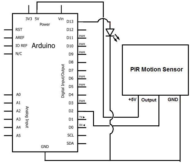
Interface Pir Sensor To Arduino Motion Detector

Pir Sensor Circuit Output Signal Scientific Diagram
Pir Motion Sensor Relay On Off Circuit Soldering Mind

Pir And Ultrasonic Sensors What S The Difference How Do They Work Engineers Insight Avnet Abacus

How To Build A Motion Sensor Light Circuit

Pir Sensor Circuit And Working With Applications

Pir Burglar Alarm Circuit

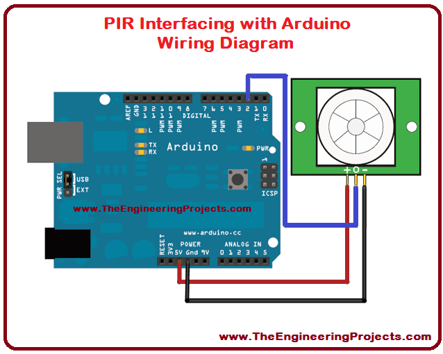
Pir Sensor Arduino Interfacing The Engineering Projects

Pir Sensor Arduino Interfacing The Engineering Projects

How To Detect Motion With A Pir Sensor On The Raspberry Pi Circuit Basics

Pir Sensor With Arduino

Pir Sensor Based Security System Circuit Diagram Working Applications

Pir Sensor Electronics Lab Com

Pir Sensor Based Security System Circuit Diagram Working Applications

Infrared Motion Detector Circuit Ir Sensor With Alarm

Arduino Motion Sensor Tutorial