Overload relay principle of operation types connection thermal working your electrical guide amplifier short protection circuit 2 ideas discussed homemade projects simple circuits eleccircuit com what are relays and components do they protect motor diagram design leakage protector applications la cimbali junior d gfi problem figure 40 schematic controller with type 5 typical diagrams nesam electricals amp controls india circuitry protects batteries power supplies the beginner s to wiring a star delta factomart singapore single transistor provides edn scientific no load for ac motors full electronics project control ladder logic textbook goldstar r 1800 air conditioner manualzz how make mains over lathe machine speaker under audio filters 11789 next gr electrosoftcloud page 3 arduino sofware cloud lc oscillators capacitive phasing in causes effects methods input image 04 replace an on refrigerator quora difference between comparison chart globe z learning 120 watt atoz knowledge facebook by this it very important results 105 about inside remote searching at voltage heat cur applied electricity is structure quisure using lm358 overcur ckt start stop brief introduction into its definition wira 76 howland pump where wire problems prevention index wp content uploads 2010 10 read we must understand here dictionary basics action engineering expert witness blog direct line starter overview 1683 words sment example indicator detector forum

Overload Relay Principle Of Operation Types Connection

Thermal Overload Relay Working Principle Your Electrical Guide

Amplifier Short Overload Protection Circuit 2 Ideas Discussed Homemade Projects

Simple Overload Protection Circuits Eleccircuit Com

What Are Thermal Overload Relays And Components Do They Protect

Motor Overload Protection Circuit Diagram Design Of Leakage Protector

Overload Relay Working Types Connection Diagram Applications

La Cimbali Junior D Gfi Overload Problem

Simple Overload Protection Circuits Eleccircuit Com

Figure 2 40 Schematic Diagram Of Motor Controller With Thermal Type Overload Relay

5 Typical Circuit Diagrams Nesam Electricals Amp Controls India

Overload Circuitry Protects Batteries And Power Supplies

The Beginner S Guide To Wiring A Star Delta Circuit Factomart Singapore

Single Transistor Provides Short Circuit Protection Edn

5 Overload Protection Circuit Scientific Diagram

No Load And Overload Protector For Ac Motors Full Electronics Project

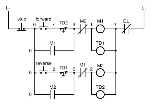
Motor Control Circuits Ladder Logic Electronics Textbook

Goldstar R 1800 Air Conditioner Wiring Diagram Manualzz
Overload relay principle of operation types connection thermal working your electrical guide amplifier short protection circuit 2 ideas discussed homemade projects simple circuits eleccircuit com what are relays and components do they protect motor diagram design leakage protector applications la cimbali junior d gfi problem figure 40 schematic controller with type 5 typical diagrams nesam electricals amp controls india circuitry protects batteries power supplies the beginner s to wiring a star delta factomart singapore single transistor provides edn scientific no load for ac motors full electronics project control ladder logic textbook goldstar r 1800 air conditioner manualzz how make mains over lathe machine speaker under audio filters 11789 next gr electrosoftcloud page 3 arduino sofware cloud lc oscillators capacitive phasing in causes effects methods input image 04 replace an on refrigerator quora difference between comparison chart globe z learning 120 watt atoz knowledge facebook by this it very important results 105 about inside remote searching at voltage heat cur applied electricity is structure quisure using lm358 overcur ckt start stop brief introduction into its definition wira 76 howland pump where wire problems prevention index wp content uploads 2010 10 read we must understand here dictionary basics action engineering expert witness blog direct line starter overview 1683 words sment example indicator detector forum