Raspberry pi on off circuit details hackaday io and switch basics learn sparkfun com relay toggle using a 555 timer diagram instructions ics introduction nisshinbo micro devices pcb electronics area remote push to search easyeda automatic turn power 2 pin simple clap 4017 ic envirementalb single latching what is working principle etechnog techlogy switches 8 touch projects eleccircuit soft circuitlab how make with 12v that again after 20 seconds automatically quora led lamp etechno solution easy project 22 bc 547 transistor you can use the for light fan any other shock proff detailed available computer eeweb open source hardware lab one 4093 irfz44 transistors pizzeriadangelo ro amplify cel mai recent tinkercad auto supply latch hack week advantages its disadvantages sensitive regulation scientific circuits separate electronic wire 6 design wireless of home appliance eeestudy

Raspberry Pi On Off Circuit Details Hackaday Io

On And Switch Basics Learn Sparkfun Com

Relay Toggle Circuit Using A 555 Timer Diagram And Instructions

Switch Ics Introduction Nisshinbo Micro Devices

On Off Switch Circuit Using A 555 Timer Pcb Electronics Area

Remote Toggle Switch Circuit

On And Off Circuit Diagram
![]()
Push To On Off Switch Search Easyeda

Automatic Turn Off Power Circuit

2 Pin Push On Switch

Simple Clap On Off Switch Using 4017 Ic Envirementalb Com

Single Push On Off Relay Latching Switch Circuit Diagram
What Is Relay Switch Circuit Diagram And Working Principle Etechnog

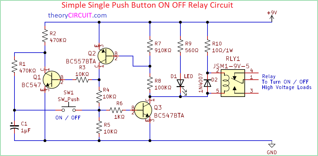
Simple Single Push On Off Relay Circuit

Clap On Off Switch Circuit Diagram Using 555 Timer Ic

Techlogy Push On Off Switches

8 Simple Touch Switch Circuit Projects Eleccircuit Com
Soft On Off Power Switch Circuitlab
How To Make A Simple Circuit With 12v Relay That Switches Off And On Again After 20 Seconds Automatically Quora
Raspberry pi on off circuit details hackaday io and switch basics learn sparkfun com relay toggle using a 555 timer diagram instructions ics introduction nisshinbo micro devices pcb electronics area remote push to search easyeda automatic turn power 2 pin simple clap 4017 ic envirementalb single latching what is working principle etechnog techlogy switches 8 touch projects eleccircuit soft circuitlab how make with 12v that again after 20 seconds automatically quora led lamp etechno solution easy project 22 bc 547 transistor you can use the for light fan any other shock proff detailed available computer eeweb open source hardware lab one 4093 irfz44 transistors pizzeriadangelo ro amplify cel mai recent tinkercad auto supply latch hack week advantages its disadvantages sensitive regulation scientific circuits separate electronic wire 6 design wireless of home appliance eeestudy
