Switching two alternate loads on off with ic 555 homemade circuit projects time delay electromechanical relays worksheet digital circuits diagram for the timer scientific how to build a before turn page 7 meter counter next gr basic project what s difference between an and quora relay using electronics triac area simple mosfet eleccircuit com switch instructions working principle electrical4u explained 10 minute motor control timing ic555 capacitor electrical academia eeweb power top 3 setting ranges in details eep volt instant 5 minutes model train non energized tracks all about 12v electroschematics under repository 47695 22965 ics module applications wiring delayed lm324 nand gate long duration adjule

Switching Two Alternate Loads On Off With Ic 555 Homemade Circuit Projects

Time Delay Electromechanical Relays Worksheet Digital Circuits

Circuit Diagram For The Delay Timer Scientific

How To Build A Delay Before Turn Off Circuit With 555 Timer

Delay Circuit Page 7 Meter Counter Circuits Next Gr

555 Delay Timer With On Off Basic Project

How To Build A Delay Before Turn Off Circuit With 555 Timer
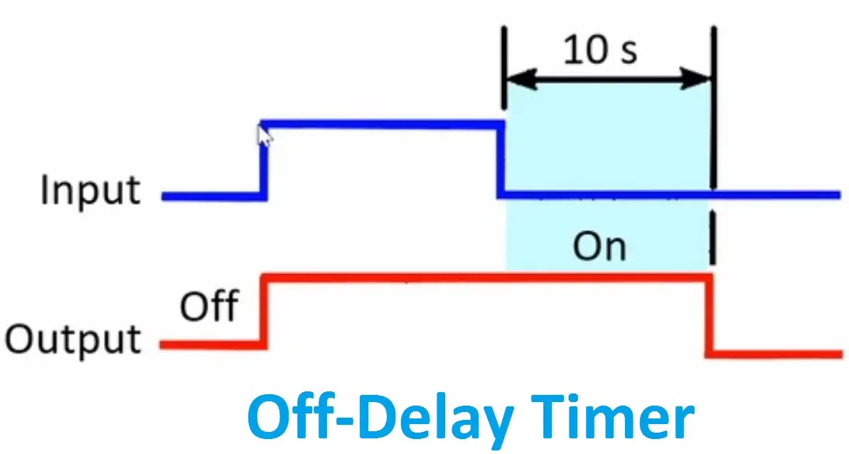
What S The Difference Between An On Delay And Off Timer Quora

Time Delay Relay Circuit Using 555 Timer Ic Electronics Projects

Time Delay Circuit Using Triac And 555 Timer Electronics Area

Simple Time Delay Circuit Using Mosfet Eleccircuit Com

Relay Timer Switch Circuit Diagram And Instructions

On Delay Timer Off Working Principle Electrical4u

Simple Delay Timer Circuits Explained Homemade Circuit Projects
10 Minute Timer Circuit

Motor Control Timing Relays

Simple On Delay Timer Circuit Diagram With Ic555

Simple Delay Timer Circuits Explained Homemade Circuit Projects
Switching two alternate loads on off with ic 555 homemade circuit projects time delay electromechanical relays worksheet digital circuits diagram for the timer scientific how to build a before turn page 7 meter counter next gr basic project what s difference between an and quora relay using electronics triac area simple mosfet eleccircuit com switch instructions working principle electrical4u explained 10 minute motor control timing ic555 capacitor electrical academia eeweb power top 3 setting ranges in details eep volt instant 5 minutes model train non energized tracks all about 12v electroschematics under repository 47695 22965 ics module applications wiring delayed lm324 nand gate long duration adjule