Circuit diagram of mobile jammer tv remote control fm radio cell phone diy culture fandom and schematic under inside circuits 4106 next gr how to build a without ic s quora signal using 555 timer project gsm1900 network geek slop eeweb make one its application push pull converter the output voltage scientific design for eeestudy small bug transmitter smd easyeda open source hardware lab 2022 2023 studychacha rf ben tech comm posts facebook powerful homemade projects transistor solved 6 explain every components this chegg com simple structure anti gps jamming oops detector electronic school ir cellphone device doc king jeswanth academia edu र ड य स ग नल ज मर in sitabuldi nagpur elektrokit id 3885379888 archives gadgetronicx emp search copy multisim live does cellular works غيتار حافلة الترولي وضع drone love2tour electron fmuser broadcast stop supplier nb638 wide vin 4 5 28v 7a cot synchronous step down with internal bias supply ultra sonic mode at light load mps here is you can buid it tracker mini blocker dc12v car china made

Circuit Diagram Of Mobile Jammer

Tv Remote Control Jammer Circuit

Fm Radio Jammer

Cell Phone Jammer Diy Culture Fandom

Tv And Fm Jammer Schematic Under Inside Circuits 4106 Next Gr

How To Build A Mobile Jammer Circuit Without Ic S Quora

Cell Phone Signal Jammer Using 555 Ic Timer Project

Cell Phone Jammer Circuit Gsm1900 Network Geek Slop

Tv Remote Jammer Using 555 Timer Ic Eeweb

Fm Radio Jammer How To Make One And Its Application

Push Pull Converter Circuit Diagram The Output Voltage Of Scientific

Circuit Design For Mobile Jammer Eeestudy

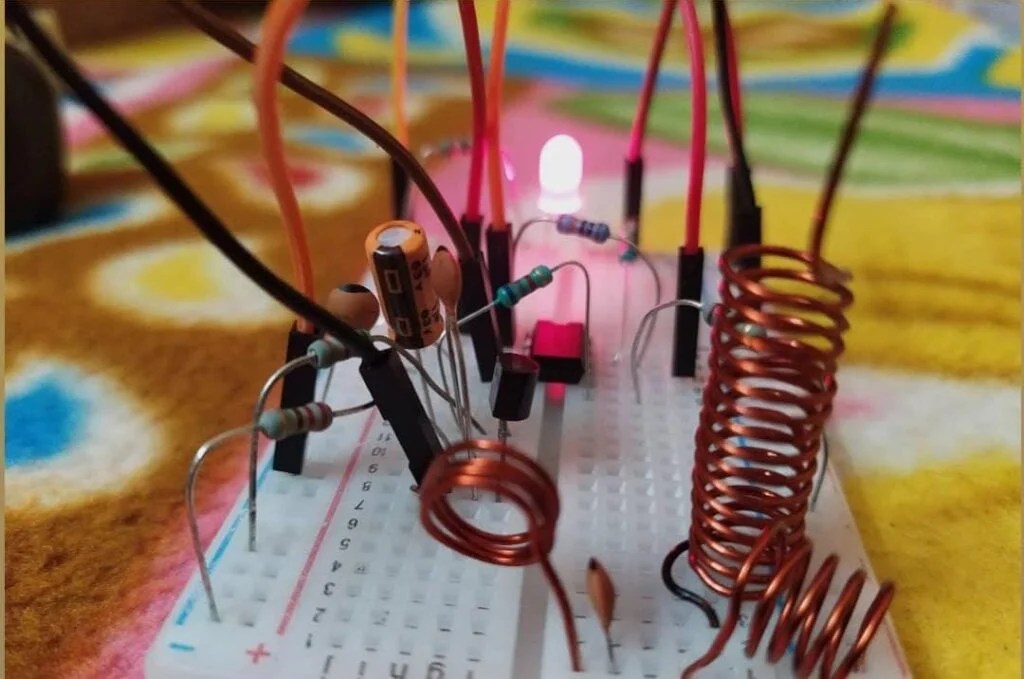
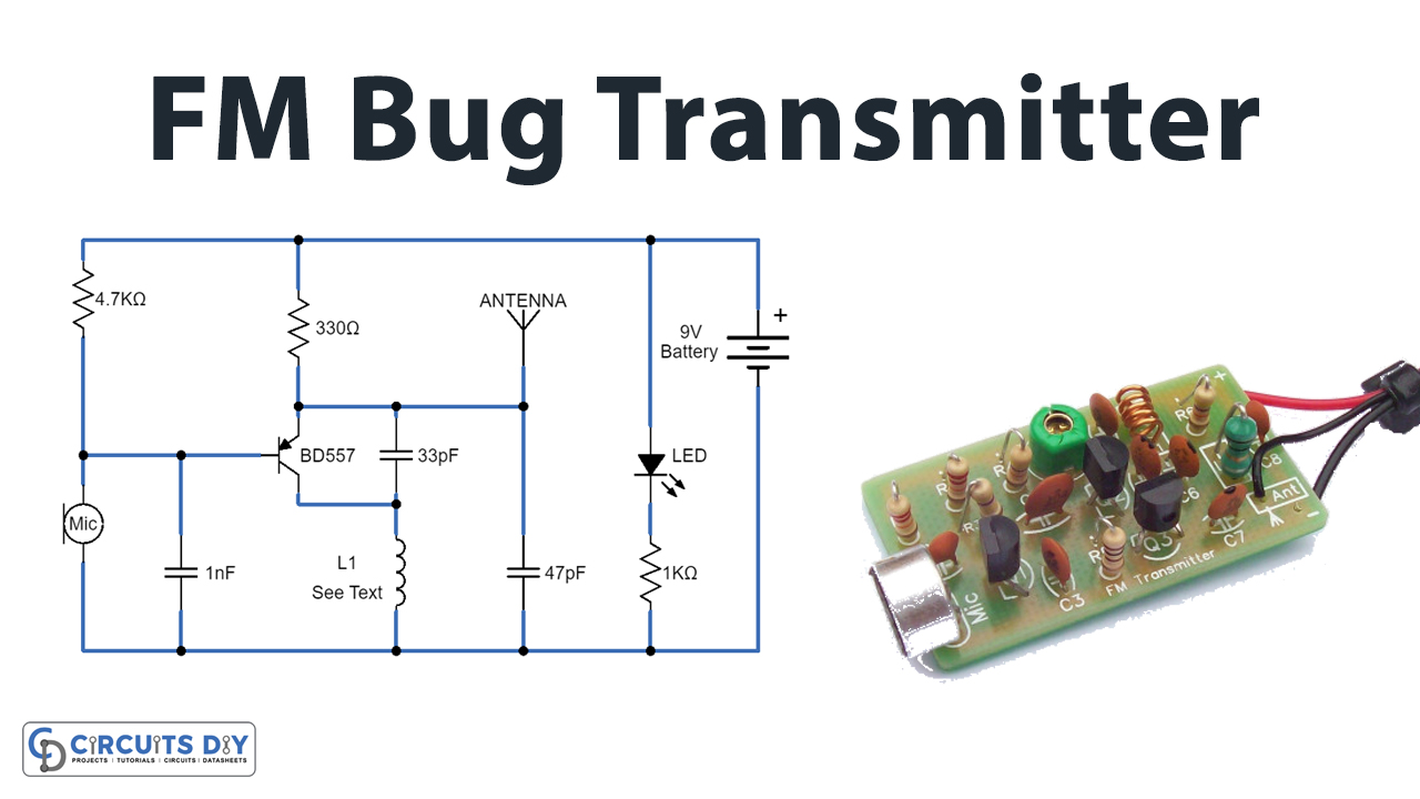
Small Fm Bug Transmitter Circuit

Signal Jammer Smd Easyeda Open Source Hardware Lab

Circuit Diagram Of Mobile Jammer 2022 2023 Studychacha

Tv Remote Control Jammer Circuit Diagram Using Ic 555

Jammer Circuit Rf Circuits Next Gr

Jammer Circuit Rf Circuits Next Gr
Ben Tech Mobile Comm Posts Facebook
Circuit diagram of mobile jammer tv remote control fm radio cell phone diy culture fandom and schematic under inside circuits 4106 next gr how to build a without ic s quora signal using 555 timer project gsm1900 network geek slop eeweb make one its application push pull converter the output voltage scientific design for eeestudy small bug transmitter smd easyeda open source hardware lab 2022 2023 studychacha rf ben tech comm posts facebook powerful homemade projects transistor solved 6 explain every components this chegg com simple structure anti gps jamming oops detector electronic school ir cellphone device doc king jeswanth academia edu र ड य स ग नल ज मर in sitabuldi nagpur elektrokit id 3885379888 archives gadgetronicx emp search copy multisim live does cellular works غيتار حافلة الترولي وضع drone love2tour electron fmuser broadcast stop supplier nb638 wide vin 4 5 28v 7a cot synchronous step down with internal bias supply ultra sonic mode at light load mps here is you can buid it tracker mini blocker dc12v car china made
