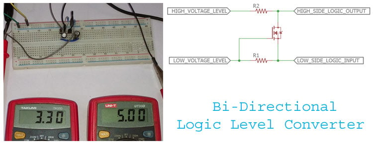
Are you curious about how logic level converters work? If so, you're in the right place. In this article, we'll explore the world of logic level converter circuit diagrams and what they can do for you.
In layman's terms, a logic level converter is an electrical circuit used to bridge the gap between two different voltage levels. The device allows signals with higher voltage levels to be converted into lower voltage levels for use in various electronic systems. A logic level converter circuit diagram is a visual representation of this process. It shows how a logic level converter works by illustrating how components are connected to each other.
The circuit diagram is divided into two parts: Input and Output. The input side displays the signals that have higher voltage levels. This power level is then lowered and sent through the logic level converter and into the output side. The output side is where the lower voltage signals end up.
When designing a logic level converter circuit, it's important to consider the required voltage levels, as well as the type of signals that need to be converted. There are a variety of types of logic level converters available, including CMOS, open-collector, and bipolar devices. Each type has its own pros and cons, so it's important to do your research and make sure you select the best device for your application.
Once you've chosen the appropriate logic level converter, the next step is to create a functioning logic level converter circuit diagram. It's best to consult a professional for help with this as there are various considerations that must be taken into account to ensure your circuit works properly. Once the diagram is complete, it should be tested before being used in your system.
Logic level converters are an essential part of many electronic systems, and the circuit diagram is the key to understanding how it works. Be sure to do your research and seek professional help when creating your own logic level converter circuit diagram.

I2c Logic Level Converter With Regulator Module Protosupplies

Logic Level Converter Schematic Networking Protocols And Devices Arduino Forum

Taking It To Another Level Making 3 3v Speak With 5v Hackaday

Bi Directional Logic Level Converter Using Mosfet

Pololu Logic Level Shifter 4 Channel Bidirectional

Bi Directional Logic Level Converter Guide Learn Sparkfun Com

5 V Ttl Signal To 12 Level Conversion

Shifting Levels Level 3 3v Microcontrollers And Neopixels Adafruit Learning System

Retired Using The Logic Level Converter Learn Sparkfun Com

Bi Directional Logic Level Converter Using Mosfet

Ws2812b And Logic Level Shifters Ledultiplexing Arduino Forum

Sparkfun Logic Level Converter Bi Directional Bob 12009 Electronics

Retired Using The Logic Level Converter Learn Sparkfun Com
Logic Level Converter Circuit Multisim Live

Pololu Logic Level Shifter 4 Channel Bidirectional

Logic Level Converter 4 Ch Bi Directional Module Protosupplies

Simple Rs232c Level Converter Using Transistors
Logic Level Converter Circuit 5v To 3 3v And Vice Versa Gadgetronicx

I2c Level Converter For 3 3v Logic Sensors And Arduino Uno