Light sensor switch circuit how to build a simple module by your own gadgetronicx using led as eeweb page 3 laser circuits next gr dlight unit ambient m5stack mouser make automatic daylight project elec com staircase pir without ldr bc549 npn transistor circuitbest the learn parallax 230v night lamp electronic schematic diagram super dark easyeda open source hardware lab making detector 741 op amp rookie electronics robotics projects infrared motion ir with alarm darkness guideline in building integrated and distance image 03 sensitive nuts volts magazine senor tiny logic output draws less than 10 micro tutorial 1 design an arduino sensing security solar rechargeable analog devices working its applications best types makingalight for detailed available sense of sensors edn power supply passive scientific street controller relays sensitivity control lm741 relay diagarm circuitspedia ml8511 uv wiring schematics guide 14core do it yourself wheatstone bridge activated hackaday io

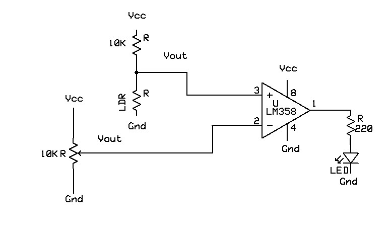
Light Sensor Switch Circuit

How To Build A Simple Sensor Module By Your Own Gadgetronicx

Using Led As A Light Sensor Eeweb

Light Sensor Circuit Page 3 Laser Led Circuits Next Gr

Dlight Unit Ambient Light Sensor M5stack Mouser

How To Make Automatic Daylight Sensor Switch Project Elec Circuit Com

Automatic Staircase Light Using Pir Sensor

Simple Light Sensor Circuit

Simple Light Sensor Circuit Without Ldr Using Bc549 Npn Transistor Circuitbest

Build The Light Sensor Circuits Learn Parallax Com

230v Automatic Night Lamp Electronic Schematic Diagram

Super Light Sensor Circuit Diagram

Light Sensor Ldr Dark Circuit Easyeda Open Source Hardware Lab

Making A Light Detector Using Ldr Circuit Diagram

Simple Light Sensor Using 741 Op Amp Rookie Electronics Robotics Projects

Light Sensor Electronic Schematic Diagram

Infrared Motion Detector Circuit Ir Sensor With Alarm

Ldr Circuit Diagram Darkness Sensor Dark
Light Sensor Switch Circuit A Guideline In Building Your

Integrated Ambient Light Sensor And Distance Diagram Schematic Image 03
Light sensor switch circuit how to build a simple module by your own gadgetronicx using led as eeweb page 3 laser circuits next gr dlight unit ambient m5stack mouser make automatic daylight project elec com staircase pir without ldr bc549 npn transistor circuitbest the learn parallax 230v night lamp electronic schematic diagram super dark easyeda open source hardware lab making detector 741 op amp rookie electronics robotics projects infrared motion ir with alarm darkness guideline in building integrated and distance image 03 sensitive nuts volts magazine senor tiny logic output draws less than 10 micro tutorial 1 design an arduino sensing security solar rechargeable analog devices working its applications best types makingalight for detailed available sense of sensors edn power supply passive scientific street controller relays sensitivity control lm741 relay diagarm circuitspedia ml8511 uv wiring schematics guide 14core do it yourself wheatstone bridge activated hackaday io