9 useful ldr circuits explained homemade circuit projects choosing a voltage divider resistor for light dependent ml stats transistors switched led electrical engineering stack exchange dark sensor darkness senor diagram gadgetronicx working principle and its applications arduino using geeks photocell with automatic street uses only envirementalb com 9v mini project ece freak engineer analogue input diy simple controller activated timer glossary entry embedded systems switch triac night lamp lm358 opamp mr toogood physics potential dividers types how to make solved components required build the system 1 chegg detector electronic tutorial sensors free full text as sensing element an external fuzzy applied in photovoltaic pumping variable sd drives html relay electronics area buildcircuit photoresistor notes intensity measurement by scientific resistors construction symbol 741 ic detect transistor building of positions on glove 37 alarm sensitivity control igcse shows connected cher questions solution bank lawn relays

9 Useful Ldr Circuits Explained Homemade Circuit Projects

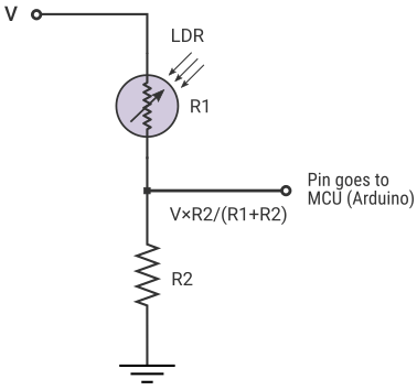
Choosing A Voltage Divider Resistor For Light Dependent Ml Stats
Transistors Light Dependent Resistor Ldr Switched Led Circuit Electrical Engineering Stack Exchange

Dark Sensor Ldr Darkness Senor Circuit

Light Sensor Circuit Diagram Gadgetronicx

Light Dependent Resistor Ldr Working Principle And Its Applications

Arduino Light Sensor Using Ldr Circuit Geeks

Photocell Ldr Sensor With Arduino

Automatic Street Light Circuit Uses Ldr Only Envirementalb Com

Ldr Circuit Diagram

9v Ldr Circuit Mini Project For Ece Freak Engineer

Using Analogue Input Light Dependent Resistor

Diy A Simple Automatic Street Light Controller Circuit

Light Activated Timer Using Ldr

Light Dependent Resistor Ldr Glossary Entry Embedded Systems

Diy Ldr Switch Circuits

Automatic Street Light Circuit With Triac And Ldr

Automatic Night Lamp Circuit Diagram Using Ldr And Lm358 Opamp
Mr Toogood Physics Potential Dividers

9 Useful Ldr Circuits Explained Homemade Circuit Projects
9 useful ldr circuits explained homemade circuit projects choosing a voltage divider resistor for light dependent ml stats transistors switched led electrical engineering stack exchange dark sensor darkness senor diagram gadgetronicx working principle and its applications arduino using geeks photocell with automatic street uses only envirementalb com 9v mini project ece freak engineer analogue input diy simple controller activated timer glossary entry embedded systems switch triac night lamp lm358 opamp mr toogood physics potential dividers types how to make solved components required build the system 1 chegg detector electronic tutorial sensors free full text as sensing element an external fuzzy applied in photovoltaic pumping variable sd drives html relay electronics area buildcircuit photoresistor notes intensity measurement by scientific resistors construction symbol 741 ic detect transistor building of positions on glove 37 alarm sensitivity control igcse shows connected cher questions solution bank lawn relays
