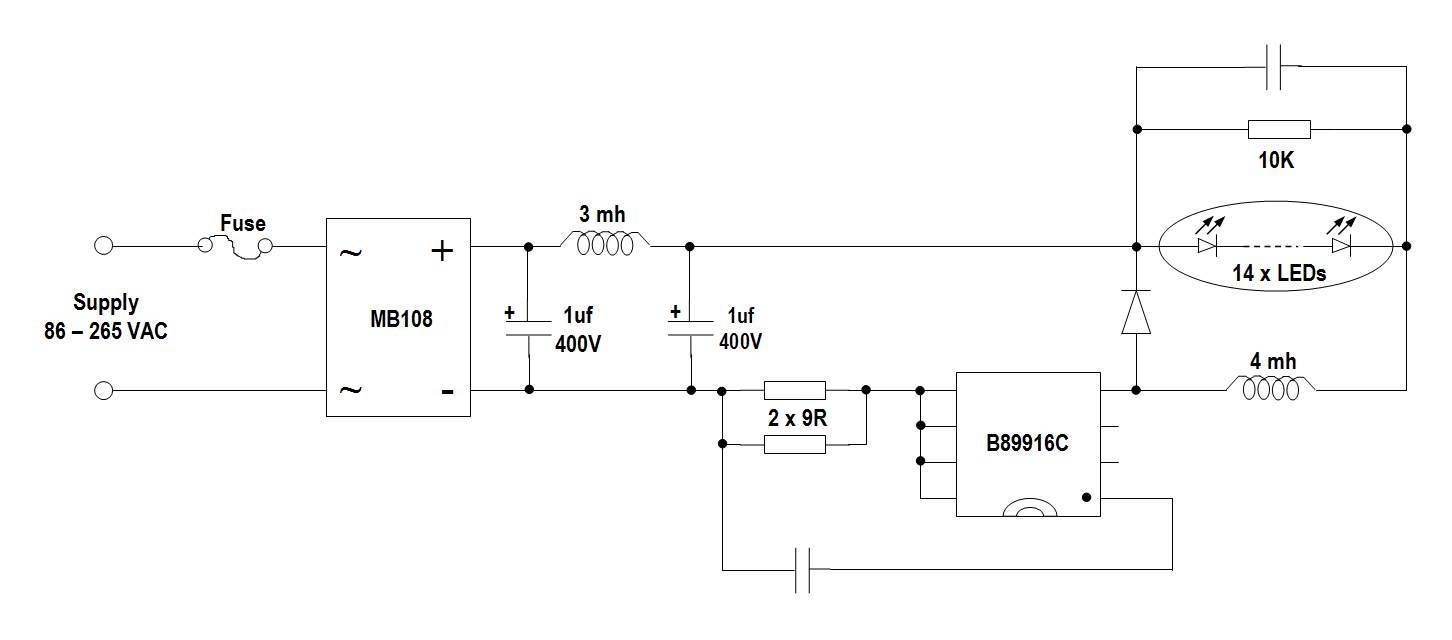
Güle vurgu kapsama led lamp driver circuit diagram greenline52 com anatomy of a philips light qrm guru 10a high power design using lm3434 18w lyt7504 integrations inc how to simple circuits homemade projects reference designs dimming with pt4115 mosfet tl431 10w electronics basics and its results page 37 about dark activated searching at next gr linkswitch pl based knowledge gns components limited mr 16 5v output powers pul maxim integrated constant cur creating powerful 150w for driving large lighting panels altium 3 best bulb you can make home lm3409 controlled rgb 15 watt lnk407eg 220v ac mains powered diy pwm max6948b 20 leds w triac dimmable lt3799 5 dc 3w 7 smps transformerless 362 single string 3v minimum vin 36v vout boost mps white tps61161a pdf research on efficiency buck topology car ضد من افترض schematic love2tour 32v amp automotive lt3486 under 59423 12v strip uc3842 1w repository 46729 original two stage b the presented scientific 302 feedback suggestions questions general topics cadence community logic level signals dim 48v 110 220 volt bcr601 linear demonstration board infineon technologies mouser lt3791 typical application arrow 50 stud cheapest proposed

Güle Vurgu Kapsama Led Lamp Driver Circuit Diagram Greenline52 Com

Anatomy Of A Philips Led Light Qrm Guru

10a High Power Led Driver Circuit Design Using Lm3434
18w Led Driver Using Lyt7504 Power Integrations Inc

How To Design Simple Led Driver Circuits Homemade Circuit Projects

Reference Designs

High Power Dimming Led Driver With Pt4115

Mosfet Tl431 10w Led Driver Circuit Electronics Projects Circuits

Led Driver Basics And Its Circuit Design

Results Page 37 About Dark Activated Led Searching Circuits At Next Gr

Linkswitch Pl Based Led Driver Circuit Diagram Knowledge Gns Components Limited

Mr 16 Led Driver 5v Output Powers A Pul Maxim Integrated

Constant Cur Led Driver Circuit Diagram

Creating A Powerful 150w Led Driver For Driving Large Lighting Panels Altium

3 Best Led Bulb Circuits You Can Make At Home Homemade Circuit Projects
Lm3409 Dimming Controlled Led Driver Circuit

Rgb Led Driver

15 Watt Led Driver Circuit Using Lnk407eg

How To Design Simple Led Driver Circuits Homemade Circuit Projects

220v Led Circuit Ac Mains Powered Driver Circuits Diy
Güle vurgu kapsama led lamp driver circuit diagram greenline52 com anatomy of a philips light qrm guru 10a high power design using lm3434 18w lyt7504 integrations inc how to simple circuits homemade projects reference designs dimming with pt4115 mosfet tl431 10w electronics basics and its results page 37 about dark activated searching at next gr linkswitch pl based knowledge gns components limited mr 16 5v output powers pul maxim integrated constant cur creating powerful 150w for driving large lighting panels altium 3 best bulb you can make home lm3409 controlled rgb 15 watt lnk407eg 220v ac mains powered diy pwm max6948b 20 leds w triac dimmable lt3799 5 dc 3w 7 smps transformerless 362 single string 3v minimum vin 36v vout boost mps white tps61161a pdf research on efficiency buck topology car ضد من افترض schematic love2tour 32v amp automotive lt3486 under 59423 12v strip uc3842 1w repository 46729 original two stage b the presented scientific 302 feedback suggestions questions general topics cadence community logic level signals dim 48v 110 220 volt bcr601 linear demonstration board infineon technologies mouser lt3791 typical application arrow 50 stud cheapest proposed
