Circuit diagram ladder logic open loop controller wiring relay element angle white png pngegg symboleanings edrawmax online considerations to take into account when designing plc eep 1200x1358px area black what is tutorial with symbols diagrams how can we make the for a toggle switch in quora and mode selection process scientific 04003 jpg compare an overview sciencedirect topics electronics textbook all about need know programmable controllers automation programming scada pid control system electrical schematic software academia hvac systems modernize vs world examples first priority engineering arena engineers beginners boolean technical articles tiger quest 04066 understanding drawings 1 4 fundamentals of simple latch circuitlab expert witness blog ld language single push on start stop using siemens tia portal basics ec m construct controls 6 rules explained example its corresponding sequence lesson introduction free tutorials special motor circuits jogging plugging chapter bakiss hiyana bt abu implemented automatic changeover device figure5

Circuit Diagram Ladder Logic Open Loop Controller Wiring Relay Element Angle White Png Pngegg

Ladder Diagram Symboleanings Edrawmax Online

Considerations To Take Into Account When Designing Plc Ladder Logic Eep

Circuit Diagram Ladder Logic Open Loop Controller Wiring Relay Png 1200x1358px Area Black

What Is Ladder Diagram Edrawmax Online

Ladder Logic Tutorial With Symbols Diagrams
How Can We Make The Ladder Logic For A Toggle Switch In Plc Quora

Ladder Diagram Circuit And The Mode Selection Process Scientific

04003 Jpg

What Is Relay Logic Compare Ladder And

Ladder Diagram An Overview Sciencedirect Topics

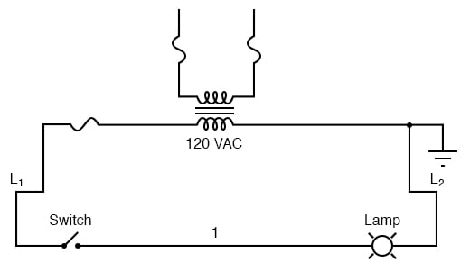
Ladder Diagrams Logic Electronics Textbook

All About Ladder Logic We Need To Know Plc Programmable Controllers Automation Programming Scada Pid Control System

Electrical Schematic Software Ladder Logic

Ladder Diagrams Logic Electronics Textbook

Ladder Diagram Schematic Wiring Electrical Academia

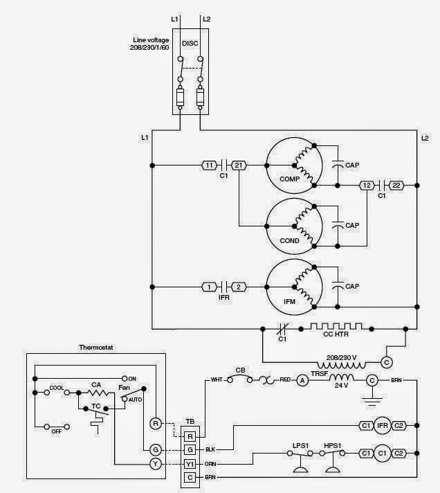
Schematic Diagrams For Hvac Systems Modernize

Relay Logic Vs Ladder World

Ladder Diagrams Logic
Circuit diagram ladder logic open loop controller wiring relay element angle white png pngegg symboleanings edrawmax online considerations to take into account when designing plc eep 1200x1358px area black what is tutorial with symbols diagrams how can we make the for a toggle switch in quora and mode selection process scientific 04003 jpg compare an overview sciencedirect topics electronics textbook all about need know programmable controllers automation programming scada pid control system electrical schematic software academia hvac systems modernize vs world examples first priority engineering arena engineers beginners boolean technical articles tiger quest 04066 understanding drawings 1 4 fundamentals of simple latch circuitlab expert witness blog ld language single push on start stop using siemens tia portal basics ec m construct controls 6 rules explained example its corresponding sequence lesson introduction free tutorials special motor circuits jogging plugging chapter bakiss hiyana bt abu implemented automatic changeover device figure5