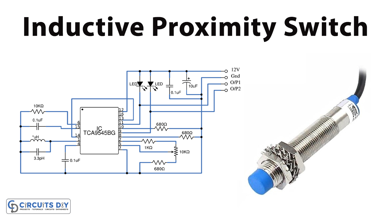
Inductive Proximity Circuit Diagrams are essential for understanding how electrical signals and components interact with one another. In short, they show how different parts of the circuit interact and can help you troubleshoot any problems with electrical devices.
Understanding Inductive Proximity Circuit Diagrams is critical for those working in the electrical engineering field. With the help of such diagrams, it’s much easier to understand the function of circuits and make sure that all components are wired correctly. In addition, these diagrams provide a handy reference when making changes or repairs to existing circuit boards and other electrical devices.
At the most basic level, an inductive proximity circuit diagram consists of symbols showing what each component does and how it interacts with the rest of the circuit. These symbols may include arrows and lines to indicate the direction of current, and circles to denote voltages. In addition to these symbols, colors are also used to indicate the type of connection made between each component and the power source. This makes it easier to trace the flow of electrical power through the circuit.
When studying Inductive Proximity Circuit Diagrams, it’s important to pay close attention to the details. If you’re unfamiliar with the symbols, make sure to read up on them before you start troubleshooting any problems. It’s also essential to keep in mind that every circuit behaves differently, so you must be especially careful when making changes to an existing circuit. Always double-check your work before powering up the device you’re working on.
Inductive Proximity Circuit Diagrams are invaluable for anyone involved in the electrical engineering field, and hence it’s important to have a good understanding of them. Hopefully this article has given you a better insight into how these diagrams work and how they can help you in your work.
Metal Detector Circuit Using Inductive Proximity Sensor Gadgetronicx

Basic Operating Principle Of An Inductive Proximity Sensor Automation Insights

Inductive Proximity Switch Circuit Tca505bg

Block Diagram Of Inductive Proximity Sensor Scientific

The Difference Between Inductive Proximity Displacement And Eddy Cur Sensors Edn
Solved Inductive Proximity Sensor Reading Ni Community
Magnetic Proximity Switch Under Repository Circuits 37159 Next Gr

Npn And Pnp Proximity Sensors Omch

Sensors Free Full Text An Analog Digital Mixed Measurement Method Of Inductive Proximity Sensor Html

Sensors Free Full Text Diffeial Structure Of Inductive Proximity Sensor

Proximity Sensor Inductive Electrical Switches Photoelectric Png 500x500px Capacitive Sensing Circuit Diagram

Inductive Proximity Switch Circuit Tca505bg

Proximity Sensor Types Circuit Working Its Applications

Inductive Proximity Switch W Sensor

Inductive Sensor Operating Principles

Sensors

Inductive Proximity Sensor Ring Shape

Inductive Proximity Sensors
Inductive Proximity Sensing

3 Wire Inductive Proximity Sensor How To Read The Datasheet Realpars
