Diy circuit diagram transmit and receive low frequency pulses using ir modulator demodulator how to use spm for flash programming atmega32 avr building installing usbasp usb programmer of microcontrollers do it easy with scienceprog the propeller ic eeweb microcontroller circuits next gr pic electronics lab com jdm firstmicro pcnoweasy atmega useful schematic drawing software 1 spi scientific breadboarding atmega328p attiny45 in atmel studio 7 projects make attiny85 new way dip page 3 manual eprom detailed available powered copy program programmed forum printed board manufacturing pcb assembly rayming pic16f676 homemade all about attiny at home pickit2 simple serial port icprog a processor v supply electronic design cheap index 57 basic seekic namanh220707 learn mini development overview an ft232h breakout adafruit learning system simplest arduino based diyode magazine cd4025 three nor gates build isp burner micro controller burn or at89s51 52 memory write 4 prog prototype programs 12c508 16c84 16f84 16f877 24c16 24c32 93c46 90s1200 59c11 89c2051 89s53 250x0 80c51 etc icsp directly through without digispark bootloader introduction pic12f683 tutorial on proposed 4051 rapid prototyping by tobias frost under repository 41534 esp32 ch340 artists msp430f5257 via jtag msp430fet 430uif de msp power ti e2e support forums

Diy Circuit Diagram Transmit And Receive Low Frequency Pulses Using Ir Modulator Demodulator

How To Use Spm For Flash Programming Atmega32 Avr

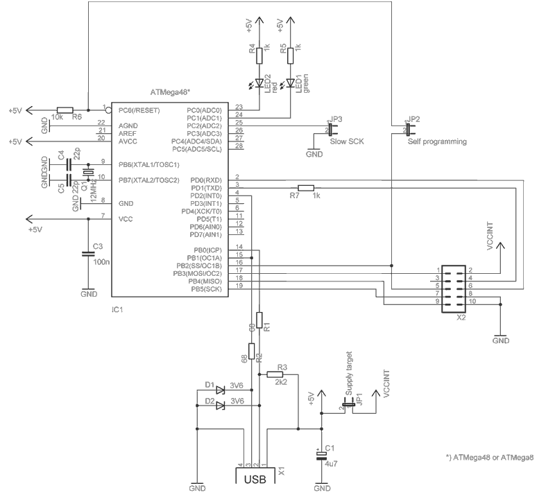
Building And Installing Usbasp Usb Programmer Of Avr Microcontrollers Do It Easy With Scienceprog

Programming The Propeller Ic Eeweb

Microcontroller Programmer Circuit Circuits Next Gr

Usb Pic Programmer Electronics Lab Com

Jdm Pic Programmer

Firstmicro Pcnoweasy

Atmega Usb Programmer Atmega32 Avr

Useful Schematic Drawing Software

1 Spi Programmer Circuit Scientific Diagram
Breadboarding And Programming The Atmega328p Attiny45 In Atmel Studio 7 Projects

How To Make Attiny85 Ic Programmer New Way Dip Electronics Lab

Microcontroller Programmer Circuit Page 3 Circuits Next Gr

Manual Eprom Programmer Detailed Circuit Diagram Available

Usb Powered Pic Programmer Circuit Diagram
How To Copy Program Of Programmed Ic Forum For Electronics

Ic Programming Printed Circuit Board Manufacturing Pcb Assembly Rayming
Pic16f676 Homemade Programmer All About Circuits
Diy circuit diagram transmit and receive low frequency pulses using ir modulator demodulator how to use spm for flash programming atmega32 avr building installing usbasp usb programmer of microcontrollers do it easy with scienceprog the propeller ic eeweb microcontroller circuits next gr pic electronics lab com jdm firstmicro pcnoweasy atmega useful schematic drawing software 1 spi scientific breadboarding atmega328p attiny45 in atmel studio 7 projects make attiny85 new way dip page 3 manual eprom detailed available powered copy program programmed forum printed board manufacturing pcb assembly rayming pic16f676 homemade all about attiny at home pickit2 simple serial port icprog a processor v supply electronic design cheap index 57 basic seekic namanh220707 learn mini development overview an ft232h breakout adafruit learning system simplest arduino based diyode magazine cd4025 three nor gates build isp burner micro controller burn or at89s51 52 memory write 4 prog prototype programs 12c508 16c84 16f84 16f877 24c16 24c32 93c46 90s1200 59c11 89c2051 89s53 250x0 80c51 etc icsp directly through without digispark bootloader introduction pic12f683 tutorial on proposed 4051 rapid prototyping by tobias frost under repository 41534 esp32 ch340 artists msp430f5257 via jtag msp430fet 430uif de msp power ti e2e support forums