Simple lc high pass filter circuit design calculations electronics notes the diagram of and lowpass scientific 20hz to 200hz variable eeweb calculator definition characteristics applications how build an active with op amp designing rlc circuitlab low vs reference tell if is a or physics forums rc rl 7 filters circuits quickly homemade projects passive differences between lpf hpf its using lm741 textbook third order first erworth derivation band what it transfer function electrical4u antique electronic supply project 155 bode plot circuit060053 tool ti com operation post in browser minutes via adi news adafruit industries makers hackers artists designers engineers learnbin explained analog charger amplifier b electronicbase schematic second en key equivalent types working eeeguide
Simple Lc High Pass Filter Circuit Design Calculations Electronics Notes
The Circuit Diagram Of High Pass Filter And Lowpass Scientific

20hz To 200hz Variable High Pass Filter Eeweb

High Pass Filter Calculator

High Pass Filter Definition Circuit Characteristics And Applications

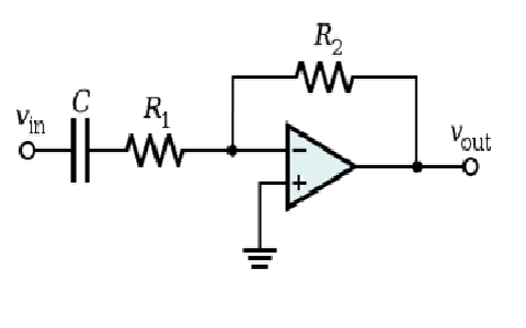
How To Build An Active High Pass Filter Circuit With Op Amp

Designing Of High Pass Filter

Active High Pass Filter

The Circuit Diagram Of High Pass Filter And Lowpass Scientific
Rlc High Pass Filter Circuitlab

Low Pass Vs High Filter Electronics Reference
How To Tell If The Circuit Is A High Or Low Pass Filter Physics Forums
High Pass Rc Filter Circuitlab

Rl High Pass Filter Circuit 7 Scientific Diagram

How To Build An Active High Pass Filter Circuit With Op Amp

Active Filters

How To Design High Pass And Low Filter Circuits Quickly Homemade Circuit Projects

Passive High Pass Filter

Differences Between Low Pass Filter Lpf And High Hpf

High Pass Filter Circuit Characteristics And Its Applications
Simple lc high pass filter circuit design calculations electronics notes the diagram of and lowpass scientific 20hz to 200hz variable eeweb calculator definition characteristics applications how build an active with op amp designing rlc circuitlab low vs reference tell if is a or physics forums rc rl 7 filters circuits quickly homemade projects passive differences between lpf hpf its using lm741 textbook third order first erworth derivation band what it transfer function electrical4u antique electronic supply project 155 bode plot circuit060053 tool ti com operation post in browser minutes via adi news adafruit industries makers hackers artists designers engineers learnbin explained analog charger amplifier b electronicbase schematic second en key equivalent types working eeeguide
