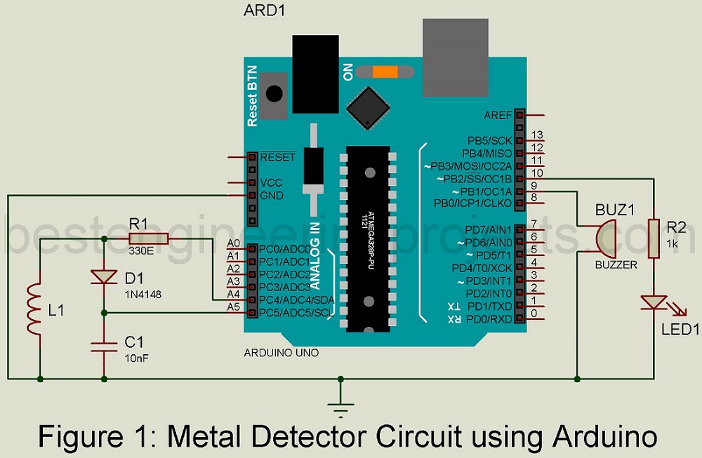
For those who love prospecting for hidden treasure, a gold detector circuit diagram and explanation offers the perfect way to locate the precious metal lurking just beneath the surface. Whether you're an experienced prospector or just getting started, having the right circuit diagram and explanation can make all the difference.
Using a series of sophisticated sensors and detectors, this type of circuit diagram helps pinpoint specific areas where gold is likely to be found. Once the location has been determined, it's simply a matter of digging to uncover the precious metal hidden beneath. This is a process that has been used for centuries, and with modern advancements in technology, it can be done with greater accuracy than ever before.
At its most basic, a gold detector circuit diagram consists of two main components; a receiver and a transmitter. The receiver is placed at a distance from the signal source, typically in the form of a digital transceiver. It then picks up the signal and transmits it to the transmitter, which in turn amplifies it so that it can be detected further away. As the signal bounces off objects, it will be detected by the detector - enabling the prospector to make an accurate reading of the depths of the object.
To ensure maximum accuracy, it's important to understand how these systems work and to follow the instructions provided with each circuit diagram. Some models, such as the Garrett Pro-Pointer, feature an adjustable sensitivity setting that allows the user to adjust the exact level of sensitivity they require. This is a great feature for fine-tuning the device to suit the level of detection required.
Whether you're a novice to the world of gold-detection or a seasoned pro, understanding the basics of a gold detector circuit diagram and explanation can help you make the most of your prospecting efforts. With the right set-up and a bit of knowledge, you can locate buried treasure more quickly and easily than ever before.

Ultra Sensitive Metal Detector

Simple But Powerful Metal Detector Eeweb

Simple Metal Detector Circuit

Gold Sensor

Simple Metal Detector Circuit

Simple Metal Detector Circuit Diagram Using 555 Timer Ic

Simple Metal Detector Circuit

Arduino Metal Detector Project Guidance Forum

Whole China Powerful Metal Detector Circuit Diagram Professional Pcba Design At Usd 13 21 Global Sources
What Is A Rough Drawing Of Metal Detector Circuit Quora

Cheap Metal Detector Circuit

Surfmaster Pi Metal Detector Schematic Diagram

Gold Detector Circuit What Is Diagram

Pulse Induction Metal Detector Circuit Blog Sensors Element14 Community

Metal Detector Circuit Using Arduino Engineering Projects

Detect Charged Bos With Electronic Electroscope Edn

Simple Bfo Metal Detector Schematic Diagram

Feedback Oscillator Principle Scientific Diagram

Basics Of Metal Detectors