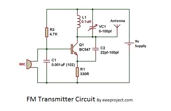
What is a Frequency Modulation Circuit Diagram?
Frequency Modulation (FM) is a technique used in radio communication to reduce the potential for interference with other signals. It works by using two different carrier frequencies that are transmitted instead of just one. This enables multiple active signals to share the same frequency without interfering with each other. A frequency modulation circuit diagram demonstrates the electrical connections required to generate and detect FM signals.
FM is widely used in commercial, broadcast, and military communications applications because it can help reduce noise, static, and distortion of other signals. FM also has the advantage of providing better voice quality than traditional amplitude modulation systems.
The basic components of an FM circuit include an oscillator, a modulator, and a demodulator. The oscillator produces a steady carrier wave at a specific frequency. The modulator varies the frequency of the wave over time to carry audio or data signals. The demodulator takes the incoming frequency-modulated signal, separates the desired signal from any unwanted noise, and converts it back into its original format.
To ensure quality transmission of your signals, the components of a frequency modulation system must be carefully interconnected. The most accurate way to achieve this is by following a circuit diagram. This diagram depicts the various electrical connections and their associated symbols, allowing the user to quickly identify the components and connect them in the correct manner.
FM technology is highly reliable, making it an ideal choice for many communication applications. As such, a correctly configured frequency modulation circuit diagram is essential for ensuring trouble-free operation. With this knowledge, you can feel confident in your ability to generate and detect FM signals in your communication systems.

Results Page 73 About Frequency Modulation 8038 Searching Circuits At Next Gr

How To Build Fm Transmitter Circuit Soldering Mind

Fm Receiver Circuit With Pcb Simple Eleccircuit Com

Frequency Modulation Using Varactor Diode

Pcb Design Practical Frequency Modulator Androiderode
Fm Modulation Circuit All About Circuits

Pll Fm Detector

Fm Transmitter Circuit With 3km Range Eee Projects

Fm Transmitter Circuit With 3km Range Eee Projects

Analog Communication Fm Modulators

Amplitude Compensation Circuit V Fm Is The Input From Frequency Scientific Diagram

Ecomms Lab Project

Led Modulation Circuits

Ic Rprecision Waveform Generator With Sweep And Frequency Modulation Under Repository Circuits 53844 Next Gr

Fm Receiver Electronics Circuit With Full Explanation

Fm Transmitter Circuit Working And Its Applications
Simplest Fm Transmitter Modulation Circuit With Bf494 Radio Frequency Transistor

How To Build An Fm Transmitter Circuit Basics
Es442 Lab 6 Frequency Modulation And Demodulation
Fm Frequency Modulation Pm Phase