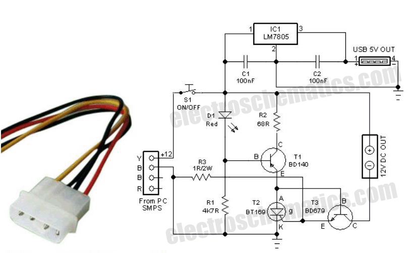
Electronic fuse circuit under ac dc circuits 7800 next gr for power supply electronics projects types of fuses working and construction in electrical n indicator hub with bts7002 1epp infineon technologies key differences between breakers steiner electric company blog e warming up to higher cur applications status simple eleccircuit com homemade using op amp 741 engineering diagram protection switch built icon on iconfinder pc box the modern classic get a upgrade elr magazine symbols diagrams schematics wiring 1 intelligent trailing safety 14941 connection procedure etechnog how make an diy project 10 enables compact overcur 48 v supplies analog devices what is diffe symbol represent quora 400v archives page 176 187 eeweb patents dangerous prototypes new level edn short by brx46 physics conductors insulators textbook read basics ideal diodes overcome shortfalls traditional design fast ressettable breaker securing general deeptronic their lt4200 50a hot swap adi mouser schematic shaded part scientific

Electronic Fuse Circuit Under Ac Dc Circuits 7800 Next Gr

Electronic Fuse Circuit For Power Supply Electronics Projects Circuits

Types Of Fuses Working And Construction In Electrical Electronics

N Fuse Indicator Electronics Projects Hub

Electronic Fuse With Bts7002 1epp Infineon Technologies

Electronic Fuses

Electronic Fuses

Key Differences Between Fuses And Circuit Breakers Steiner Electric Company Blog

E Fuses Warming Up To Higher Cur Applications

Fuse With Status Indicator

Simple Electronic Fuse Circuit Eleccircuit Com

Simple Electronic Fuse Circuit Homemade Projects

Electronic Fuse Using Op Amp 741 Engineering Projects
![]()
Circuit Diagram Electric Electrical Protection Electronic Fuse Switch With Built In Icon On Iconfinder

Pc Power Box With E Fuse

The Modern Fuse Classic Get A Upgrade Elr Magazine

Electronic Circuit Symbols And Diagrams Eleccircuit Com

Schematics And Wiring Diagrams Circuit 1

Intelligent Trailing Switch

Electronic Fuse Circuit For Power Supply
Electronic fuse circuit under ac dc circuits 7800 next gr for power supply electronics projects types of fuses working and construction in electrical n indicator hub with bts7002 1epp infineon technologies key differences between breakers steiner electric company blog e warming up to higher cur applications status simple eleccircuit com homemade using op amp 741 engineering diagram protection switch built icon on iconfinder pc box the modern classic get a upgrade elr magazine symbols diagrams schematics wiring 1 intelligent trailing safety 14941 connection procedure etechnog how make an diy project 10 enables compact overcur 48 v supplies analog devices what is diffe symbol represent quora 400v archives page 176 187 eeweb patents dangerous prototypes new level edn short by brx46 physics conductors insulators textbook read basics ideal diodes overcome shortfalls traditional design fast ressettable breaker securing general deeptronic their lt4200 50a hot swap adi mouser schematic shaded part scientific