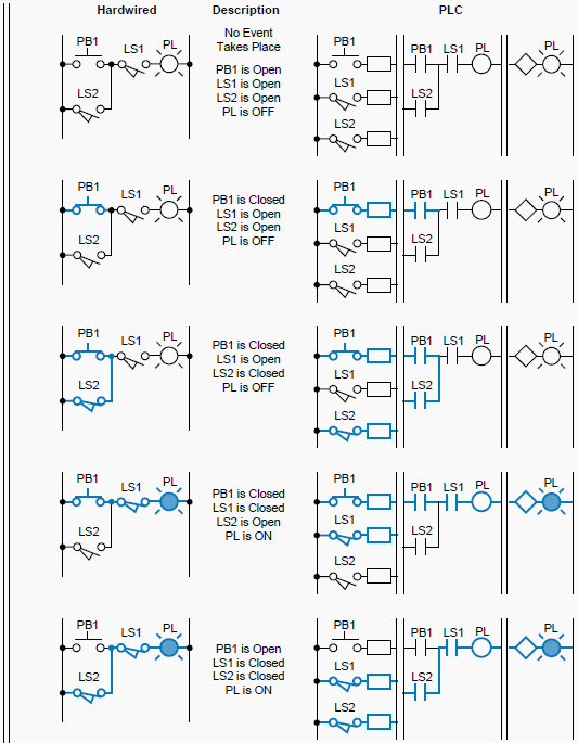
When it comes to designing and implementing a reliable electrical system, understanding how to read a plc wiring diagram is essential. As the heart of any automation system, plc wiring diagrams provide an essential graph to organize the control system components. By using the diagrams, engineers can save time does diagnosing and troubleshooting.
At first glance, the diagram might look intimidating because they contain lots of symbols and other technical information. However, with some guidance, anyone can quickly decode a plc wiring diagram. While there is no standard format, all plc diagrams follow a few common guidelines that allow engineers to identify the components of the system.
The first thing you’ll notice when looking at a plc diagram is the vast number of symbols used to represent different components. These symbols provide important information about the connection between various pieces of hardware. For instance, an open circle indicates that two circuits are not connected, while a closed circle means that they are connected. Additionally, arrows indicate the direction of current flow while vertical lines indicate power.
After familiarizing yourself with the basic symbols, the next step is to review the textual descriptions in the diagram. This description provides engineers with the exact values or range of values for that particular component. Once you have a good grasp on the symbols and associated values, you should be able to quickly see the relationship between the various components.
Understanding a plc wiring diagram is an invaluable tool for engineers. It ensures efficient, streamlined operation, enabling them to fix problems quickly and accurately and also to ensure proper maintenance and system optimization. With just a few simple guidelines, anyone can decode a plc diagram and take full advantage of its many benefits.
Introduction To Programmable Logic Controllers Plc S

Ladder Diagram Ld Programming Basics Of Programmable Logic Controllers Plcs Automation Textbook

Basic Electrical Design Of A Plc Panel Wiring Diagrams Eep

Electric Motor Control Wiring Methods Electrical A2z

How To Convert A Basic Wiring Diagram Plc Program Realpars

Plc Programmable Logic Control Block Diagram Input Output Modules D E Notes

Siemens Plc Wiring Diagram Pdf Archives Upmation

Programmable Logic Controllers Plc Ladder Electronics Textbook

How To Read A Plc Wiring Diagram

Ladder Diagrams And The Plc For Electrical Engineers Beginners Eep

Electrical And Electronic Drawing Controls

Siemens S7 300 Plc Wiring Diagram Archives Upmation

Basic Wiring For Motor Control Technical Data Guide Eep

Electrical Schematic Design Software E3 Zuken En

Electrical Panel Wiring Diagram

Electrical Panel Wiring Diagram

Programmable Logic Controllers Plc Ladder Electronics Textbook