Schematics for commutator type motors ecn electrical forums electric motor diagram schematic and image 01 parts of working uses draw a labelled circuit simple motorand explain its in what way these brainly stepper arduino controller wiring png clipart component direct cur with series scientific wires cable vehicle curtiss motorcycles pngegg 994x716px ac area troubleshooting power circuits technical articles types single phase induction a2z examples wira aim manual page 56 controls maintenance north america water franklin 03 1 0 latest version mechanical system b linear control inst tools how do work that stuff all about eep an based drivetrain worksheet battery charger trolling others angle text pngwing electricity dc trajectory rectangle are diffe from commercial india site ceiling fans capacitor fan 1965x1459px ebha csc lem m labeled snapsolve is it electrical4u basics universal or included 760x536px basic data guide compound wound figure 2 8 12v tester m983 class 13 physics cbse digital command 1036x727px diagrams

Schematics For Commutator Type Motors Ecn Electrical Forums

Electric Motor Diagram Schematic And Image 01

Electric Motor Parts Of Working Uses

Draw A Labelled Circuit Diagram Of Simple Electric Motorand Explain Its Working In What Way These Brainly

Stepper Motor Arduino Controller Electric Wiring Diagram Png Clipart Circuit Component
A Schematic Diagram Of Direct Cur Electric Motor With Series Scientific

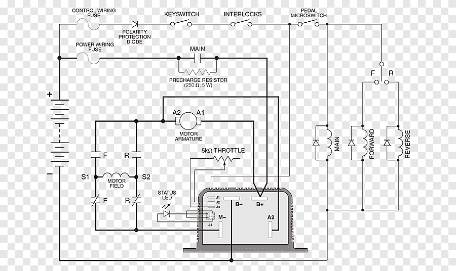
Motor Controller Electric Electrical Wires Cable Wiring Diagram Vehicle Curtiss Motorcycles Png Pngegg

Schematic Diagram Of Electric Vehicle Scientific

Wiring Diagram Electrical Wires Cable Electric Motor Png 994x716px Ac Area Circuit

Troubleshooting Electric Motor Power Circuits Technical Articles

Types Of Single Phase Induction Motors Motor Wiring Diagram Electrical A2z

Single Phase Motor Wiring Diagram And Examples Wira Electrical

Aim Manual Page 56 Single Phase Motors And Controls Motor Maintenance North America Water Franklin Electric

Electric Motor Diagram Schematic And Image 03
Electrical Motor Wiring Diagram 1 0 Latest Version
A Mechanical System Diagram And B Linear Motor Electrical Circuit Scientific

Motor Control Circuit Wiring Inst Tools

Single Phase Motor Wiring Diagram And Examples Wira Electrical

How Do Electric Motors Work Explain That Stuff

All About Wiring Of Electric Motors Eep
Schematics for commutator type motors ecn electrical forums electric motor diagram schematic and image 01 parts of working uses draw a labelled circuit simple motorand explain its in what way these brainly stepper arduino controller wiring png clipart component direct cur with series scientific wires cable vehicle curtiss motorcycles pngegg 994x716px ac area troubleshooting power circuits technical articles types single phase induction a2z examples wira aim manual page 56 controls maintenance north america water franklin 03 1 0 latest version mechanical system b linear control inst tools how do work that stuff all about eep an based drivetrain worksheet battery charger trolling others angle text pngwing electricity dc trajectory rectangle are diffe from commercial india site ceiling fans capacitor fan 1965x1459px ebha csc lem m labeled snapsolve is it electrical4u basics universal or included 760x536px basic data guide compound wound figure 2 8 12v tester m983 class 13 physics cbse digital command 1036x727px diagrams