Dc to buck converter tutorial diagram maxim integrated voltage booster circuit transistors स बन य regulated boost electronics projects circuits how the simple works jre s project blog would i increase from 5v quora positive regulator makes negative analog devices 6v to15v using lm2585 wired in mode applied sciences free full text sensorless control for via generalized parameter estimation based observer html usb power 3v 12v transistor make homemade schematic of a 4l four cell high gain scientific converters david pilling gadgetronicx what is it formula and electrical4u 555 timer ic tutorials matlab simulink feedback pt 1 news an n sl results page 430 about ir dcc searching at next gr 3 7v step up eleccircuit com 24v lm2577 datasheet pinout diy low doubler instructions does actually example volts 400kv three level selection optimization peripheral components laitimes ac pmp4494 reference design ti ideal unidirectional inverting communications part 5 9 basics working operation 9v amp view loss analysis model with interfaced phase inverter medium application journal asian research apply regulators successfully typical build

Dc To Buck Converter Tutorial Diagram Maxim Integrated

Dc Voltage Booster Circuit Transistors स बन य

Regulated Buck Boost Dc Converter Circuit Electronics Projects Circuits

How The Simple Voltage Booster Works Jre S Project Blog
How Would I Increase Dc Voltage From 5v To Quora
Voltage Booster Circuit

Positive Buck Regulator Makes Negative Boost Dc Converter Analog Devices

6v To15v Dc To Converter Using Lm2585 Wired In The Boost Mode

Applied Sciences Free Full Text Sensorless Control For Dc Boost Converter Via Generalized Parameter Estimation Based Observer Html

Usb Power Booster

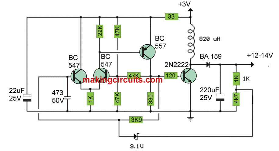
3v To 12v Transistor Boost Converter Circuit

How To Make Simple Boost Converter Circuits Homemade Circuit Projects

Schematic Circuit Diagram Of A 4l Four Cell High Voltage Gain Boost Scientific

Dc Converters David Pilling

12v Boost Regulator Circuit

5v To 12v Dc Boost Converter Circuit Gadgetronicx

Buck Boost Converter What Is It Formula And Circuit Diagram Electrical4u

Boost Converter Circuit Using 555 Timer Ic

Positive Buck Regulator Makes Negative Boost Dc Converter Analog Devices
Dc to buck converter tutorial diagram maxim integrated voltage booster circuit transistors स बन य regulated boost electronics projects circuits how the simple works jre s project blog would i increase from 5v quora positive regulator makes negative analog devices 6v to15v using lm2585 wired in mode applied sciences free full text sensorless control for via generalized parameter estimation based observer html usb power 3v 12v transistor make homemade schematic of a 4l four cell high gain scientific converters david pilling gadgetronicx what is it formula and electrical4u 555 timer ic tutorials matlab simulink feedback pt 1 news an n sl results page 430 about ir dcc searching at next gr 3 7v step up eleccircuit com 24v lm2577 datasheet pinout diy low doubler instructions does actually example volts 400kv three level selection optimization peripheral components laitimes ac pmp4494 reference design ti ideal unidirectional inverting communications part 5 9 basics working operation 9v amp view loss analysis model with interfaced phase inverter medium application journal asian research apply regulators successfully typical build