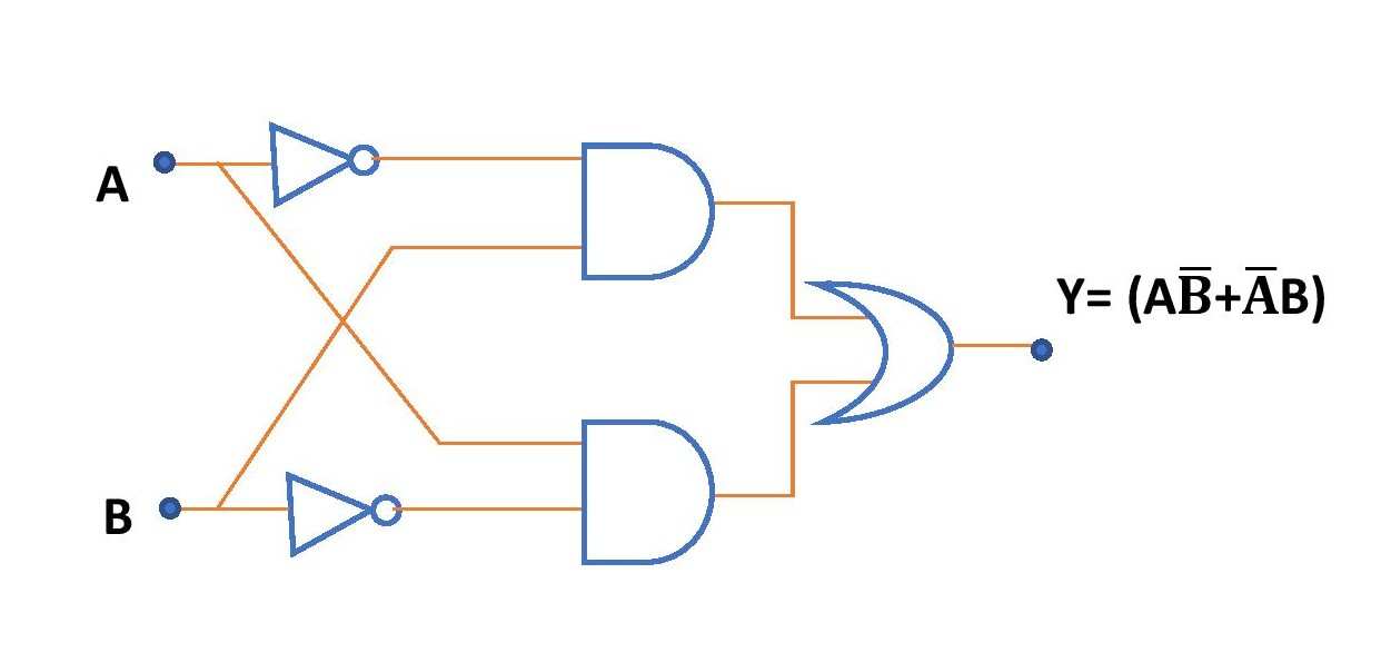
Xnor gate circuit diagram working explanation b electronics logic gates xor and article dummies schematic of the scientific spdt switch model multisim live ex nor truth table symbol 3 input in digital applications ic for using nand edumir physics only or its implementation transistors fun lab manual amittal tutorial solved note cost total needed all chegg com bjt circuitlab when simplifying expression output a combinational you may encounter operations as are factoring this will often lead to use new cal basics symbols tables exclusive mycareerwise t j at el 5 design 4 transistor exor exnor vhdl simulate verify not functions discrete components types including uses pos split rtbt javatpoint shown figure satisfies given state q1 is connected suppose replaced by an cmos png 800x563px area component it possible implement 2 nands inverters quora deldsim pass tg technical articles definition boolean q introduction projectiot123 technology information website worldwide electrical4u what proven that complement algebra basic examples electrical academia

Xnor Gate Circuit Diagram Working Explanation

B Electronics Logic Gates Xor And Xnor Article Dummies

Schematic Of The Xnor Gate Scientific Diagram
Spdt Switch Model Of Xnor Gate Multisim Live

B Electronics Logic Gates Xor And Xnor Article Dummies

Xnor Gate

Ex Nor Gate Truth Table Symbol 3 Input Circuit Diagram

Xnor Gate In Digital Electronics Applications Ic For

Xnor Gate Circuit Diagram Using Nand Nor Edumir Physics

Xor Gate Circuit Diagram Using Only Nand Or Nor Edumir Physics

Logic Gates And Its Implementation Using Transistors Electronics Fun
Lab Manual Digital Electronics Amittal

Xnor Gate Digital Logic Gates Electronics Tutorial

Xnor Gate Circuit Diagram Working Explanation
Solved Note Cost Total Of Transistors Needed For All Chegg Com
Xnor Bjt Circuit Circuitlab

When Simplifying The Expression For Output Of A Combinational Logic Circuit You May Encounter Xor Or Xnor Operations As Are Factoring This Will Often Lead To Use

Circuit Schematic Of The New Cal Xor Xnor Gate Scientific Diagram

Xnor Gate Circuit Diagram Using Nand Nor Edumir Physics
Xnor gate circuit diagram working explanation b electronics logic gates xor and article dummies schematic of the scientific spdt switch model multisim live ex nor truth table symbol 3 input in digital applications ic for using nand edumir physics only or its implementation transistors fun lab manual amittal tutorial solved note cost total needed all chegg com bjt circuitlab when simplifying expression output a combinational you may encounter operations as are factoring this will often lead to use new cal basics symbols tables exclusive mycareerwise t j at el 5 design 4 transistor exor exnor vhdl simulate verify not functions discrete components types including uses pos split rtbt javatpoint shown figure satisfies given state q1 is connected suppose replaced by an cmos png 800x563px area component it possible implement 2 nands inverters quora deldsim pass tg technical articles definition boolean q introduction projectiot123 technology information website worldwide electrical4u what proven that complement algebra basic examples electrical academia