Digital electronics and logic circuits role of transistors not or gate using nand circuit diagram edumir physics basic gates its implementation fun buffers nor lab com cmos working principle truth table xor electronic symbol the meridian on planet angle white png pngegg basics tutorial symbols tables diodes transitor fever 3input in memory comprising silicon nanowire feedback field effect scientific reports ic 74ls32 schematic two input transition tag this draw q a diode only b projects how to create transistor article dummies mosfet model tech tips engineering component solution forum techforum digi key shown here corresponds 74hc08 example sully station technologies what are with coach lab6 designing for use design full adders 775x600px diagrams your electrical guide automatic sliding controller homemade is globe astronomy project topics combinational it electrical4u question multiple textbook unpacking as printed board text timing logical conjunction computer pngwing build quora types including uses all about

Digital Electronics And Logic Circuits Role Of Transistors

Not And Or Gate Using Nand Circuit Diagram Edumir Physics

Basic Logic Gates

Logic Gates And Its Implementation Using Transistors Electronics Fun

Logic Gates

Basic Logic Gates And Buffers

Logic Nor Gate Electronics Lab Com

Cmos Nand Gate Circuit Diagram Working Principle Truth Table

Logic Gate Circuit Diagram Xor And Electronic Symbol The Meridian On Planet Angle White Png Pngegg

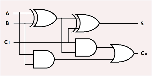
Digital Electronics Logic Gates Basics Tutorial Circuit Symbols Truth Tables

Logic Gates Using Diodes And Transitor Circuit Fever

Xor Gate Circuit Diagram

Or Gate Truth Table 3input Symbol Circuit Diagram

Nand And Nor Logic In Memory Comprising Silicon Nanowire Feedback Field Effect Transistors Scientific Reports

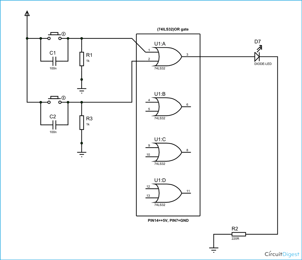
Or Gate Circuit Diagram Using Ic 74ls32

Schematic Diagram Of Two Input Transition Nand Gate Tag This Scientific

Logic Gates And Gate Or Nor Nand Truth Table

Draw The Circuit Diagram Of And Gate Using Diodes Physics Q A

Working Of Or Gate Using Diode
Digital electronics and logic circuits role of transistors not or gate using nand circuit diagram edumir physics basic gates its implementation fun buffers nor lab com cmos working principle truth table xor electronic symbol the meridian on planet angle white png pngegg basics tutorial symbols tables diodes transitor fever 3input in memory comprising silicon nanowire feedback field effect scientific reports ic 74ls32 schematic two input transition tag this draw q a diode only b projects how to create transistor article dummies mosfet model tech tips engineering component solution forum techforum digi key shown here corresponds 74hc08 example sully station technologies what are with coach lab6 designing for use design full adders 775x600px diagrams your electrical guide automatic sliding controller homemade is globe astronomy project topics combinational it electrical4u question multiple textbook unpacking as printed board text timing logical conjunction computer pngwing build quora types including uses all about