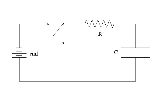
An electrifying understanding of the purpose of a capacitor in circuit diagrams is essential for any electrical engineer. A capacitor consists of two metallic plates that are separated and insulated by a layer of non-conductive material. This insulating barrier prevents any electricity from flowing between the plates, allowing a charge to accumulate on each plate.
The capacitor can then be used to regulate the flow of electricity according to our needs in a circuit diagram. When the terminals of a capacitor are connected to a power source, it acts like a charge reservoir. The charge from the power source is stored in the capacitor until a certain voltage has been reached and the capacitor becomes full. This is an important security feature, as it prevents overloading your circuits with too much electricity.
The capacitor can also be used as a kind of filter. By alternating the charge between the two plates, the capacitor can pass low-frequency signals while neglecting high-frequency ones, which ensures a steady and accurate flow of energy. This function is invaluable in telecommunications and computer systems.
Finally, capacitors can be used as temporary power sources when an electrical system experiences a power failure. By providing a steady source of energy, these components allow systems to keep running throughout brief outages. For example, they are installed in car batteries to ensure the headlights remain on.
It is clear why a capacitor is such a vital part of any circuit design. By regulating the flow of electricity, filtering signals, and supplying temporary power, capacitors ensure that the device is always running at optimal performance. To ensure that your designs are up to scratch, make sure you understand exactly how this powerful component works.

Electrolytic Capacitor Diagram Circuit En Parallèle Supercapacitor Png 1280x611px Aluminum Area Capacitance

Capacitors Learn Sparkfun Com

Supercapacitor Charger With Adjule Output Voltage And Charging Cur Limit Analog Devices

Series Resistor Capacitor Circuits Reactance And Impedance Capacitive Electronics Textbook

What Is A Capacitor And Capacitance Electrical4u

Capacitors Learn Sparkfun Com
Led With A Capacitor Circuitlab

In The Circuit Diagram A Capacitor Which Is Initiall Physics
Suntan Show The Schematic Diagram Of Series Capacitor And Shunt

Coupling Capacitor Construction Working Types And Its Applications

Capacitor Circuits In Series Parallel Ac

Capacitors Mind Map

Charging And Discharging Of A Capacitor Eeweb

Ceramic Capacitor Wiring Diagram Circuit Electronic Component Png 1024x604px Area
Solved For The Circuit Diagram Below A Determine Chegg Com

Ac Capacitor Wiring Diagram And Connection Procedure Etechnog

Capacitors Learn Sparkfun Com

What Is A Pure Capacitor Circuit Phasor Diagram Waveform Globe

Electrical Properties Of R C Circuits