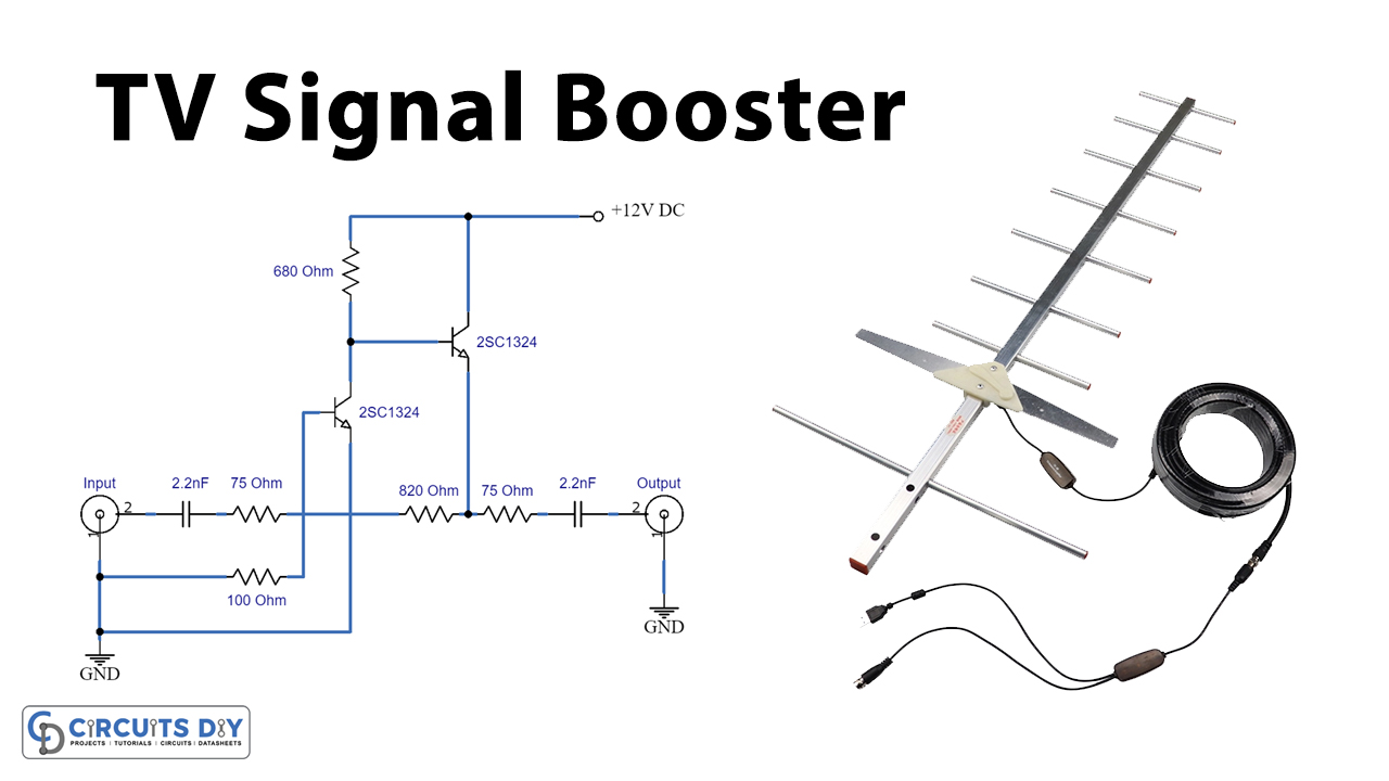
An amplifier circuit can do much more than just boost signals; it can also help you build your own sound system. If you’ve ever wondered how to make an amplifier from scratch, then look no further.
A booster amplifier schematic diagram is a detailed diagram that shows the components and connections of the amplifier and its power source. This diagram can be used to build or adjust the amplifier’s performance and to ensure that it works correctly.
The basic parts of a booster amplifier schematic diagram include the input, output, power supply, components of the feedback loop and the current supply. The input is where the signal enters the amplifier, while the output is where it leaves, typically connected to a speaker or headphones. The power supply provides the energy necessary to drive the amplifier, while the components of the feedback loop ensure the amplifier works correctly. Finally, the current supply ensures the amplifier works correctly across different types of voltage and current levels.
When you’re building an amplifier from scratch, the schematic diagram is key. It’s easier to understand than more complex diagrams – all of the components are clearly labeled, and even the wiring is easy to follow. With a few clicks, you can add or remove components, adjust the feedback loop, or make any other necessary changes. You can also test the amplifier’s performance using the schematic diagram, making sure it’s working as it should.
So if you’re looking to build your own custom sound system, creating your own amplifier circuit is a great place to start. A booster amplifier schematic diagram will give you all the necessary information to build the best-sounding amplifier you can. With the right knowledge, you can craft a powerful amplifier to bring amazing sound to your home.

150 Watt Amplifier Circuit

Bi Directional 2 4 Ghz One Watt Amplifier With Receive Pre Amp

Cable Tv Signal Booster Amplifier

Antenna Project Page 2 Circuits Rf Next Gr
Kutingting Ph Posts Facebook

Fm Antenna Booster Circuit

Given The Schematic Diagram Of A 50 Watt Booster Amplifier And Its Pictorial Write Name Brainly Ph

150 Watt Amplifier Circuit

Audio Booster Circuit Diagram And Instructions

Simple 50 Watt Power Amplifier Circuit Homemade Projects

25 Watt Power Amplifier Circuit Diagram Seekic Com

How To Make Audio Power Amplifier Circuit Electronic Projects Design Ideas Electronics Lab Com Community

Simple 150 Watt Amplifier Circuit Using Transistors Homemade Projects

Transistor Stereo Bass Booster Circuit Projects

Fm Antenna Amplifier Circuit

Tv Antenna Booster

Uhf Antenna Amplifier Circuit

Circuit Zone Com Electronic Kits Projects Schematics Diy Electronics

Simple Treble Booster Circuit

Bi Directional 2 4 Ghz One Watt Amplifier With Receive Pre Amp
