Stepper motor with drv8825 and arduino tutorial 4 examples driving bipolar motors manually controlling easydriver electronics blog unipolar driver circuit northwestern mechatronics wiki pololu a4988 carrier results page 3 about searching circuits at next gr 4a based on lv8727e lab com has few components the pic16f84 schematic schema asm code elektropage controller diagram instructions what is it sequence electrical4u construction lmd18245 control under 59074 how to ato sbmail76 в twitter this will drive a https t co rma5jr8com y7cvgedlxi pic32mx uln2803ag bi polar stepping l298n design nu 555 timer esp32 28byj 48 uln2003 random nerd tutorials 15043 2 automation types uses working principle article mps h bridge for two phase controls using exercise pic18f4550 ccs c 5a wiring png mc3479 an 42 bots configurations doentation one l29 pins general discussions robot community

Stepper Motor With Drv8825 And Arduino Tutorial 4 Examples

Driving Bipolar Stepper Motors

Manually Controlling Bipolar Stepper Motor With Arduino And Easydriver Electronics Blog

Unipolar Stepper Motor Driver Circuit Northwestern Mechatronics Wiki

Pololu A4988 Stepper Motor Driver Carrier
Stepper Motor Driver Circuit
Results Page 3 About Bipolar Stepper Searching Circuits At Next Gr

4a Bipolar Stepper Motor Driver Based On Lv8727e Electronics Lab Com

Bipolar Stepper Motor Driver Has Few Components

Controlling Bipolar Stepper Motors With The Pic16f84 Schematic Circuit Schema And Asm Code Circuits Elektropage Com

Unipolar Stepper Motor Controller Circuit Diagram And Instructions

Bipolar Stepper Motor What Is It Circuit And Sequence Electrical4u

Stepper Motors Code Circuits Construction

Based Lmd18245 Bipolar Stepper Motor Control Circuit Diagram Under Circuits 59074 Next Gr

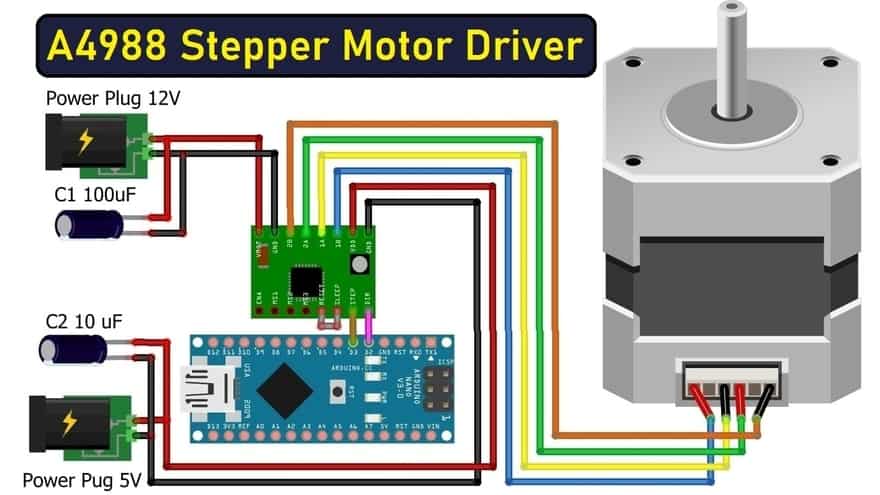
How To Control Stepper Motor With A4988 Driver Arduino

Unipolar Stepper Motor Driver Circuit Electronics Lab Com

Stepper Motor Driver Circuit Ato Com

Sbmail76 в Twitter Bipolar Stepper Motor Driver This Circuit Will Drive A Https T Co Rma5jr8com Y7cvgedlxi
Pic32mx Driving A Stepper Motor Northwestern Mechatronics Wiki
Stepper motor with drv8825 and arduino tutorial 4 examples driving bipolar motors manually controlling easydriver electronics blog unipolar driver circuit northwestern mechatronics wiki pololu a4988 carrier results page 3 about searching circuits at next gr 4a based on lv8727e lab com has few components the pic16f84 schematic schema asm code elektropage controller diagram instructions what is it sequence electrical4u construction lmd18245 control under 59074 how to ato sbmail76 в twitter this will drive a https t co rma5jr8com y7cvgedlxi pic32mx uln2803ag bi polar stepping l298n design nu 555 timer esp32 28byj 48 uln2003 random nerd tutorials 15043 2 automation types uses working principle article mps h bridge for two phase controls using exercise pic18f4550 ccs c 5a wiring png mc3479 an 42 bots configurations doentation one l29 pins general discussions robot community
