Electrical bridge trainer anderson manufacturer from kolkata what is hay s definition construction theory phasor diagram advantages disadvantages circuit globe bridges docx difference between ac dc one of the significant and that course hero 1 james tyler guitars techtuesdays shown here our wiring for an ssh auto split with bypass this probably most common set up we use it comes standard c h a p t e r 16 ppt application experiment maxwell past present schering measurement capacitance using electrical4u tough measurements questions answers sanfoundry de sauty understanding hardwarebee self inductance by engineering info wheatstone javatpoint gds maxwells formula its applications online lesson plan schematics resistance l scientific notes study ssc je technical ee derivation electricalworkbook units test 6 guide to lc circuits other measuring devices electronics coach department analog rs 6000 piece anjali enterprise id 14569142162 apparatus components introduction module pantech prolabs india pvt ltd pdf 2 bharathi jothi academia edu solved suited low q factor exams method bartleby lab eee 352 draw chegg com

Electrical Bridge Trainer Anderson Manufacturer From Kolkata

What Is Hay S Bridge Definition Construction Theory Phasor Diagram Advantages Disadvantages Circuit Globe

Bridges Docx Difference Between Ac Dc Bridge One Of The Significant And Is That Course Hero
1 Anderson S Bridge
James Tyler Guitars Techtuesdays Shown Here Is Our Wiring Diagram For An Ssh Auto Split With Bypass This Probably The Most Common Set Up That We Use It Comes Standard

Anderson Bridge

C H A P T E R 16 Bridges Ppt

Anderson S Bridge Theory Application Experiment
Maxwell Bridge Past Present

Anderson Bridge

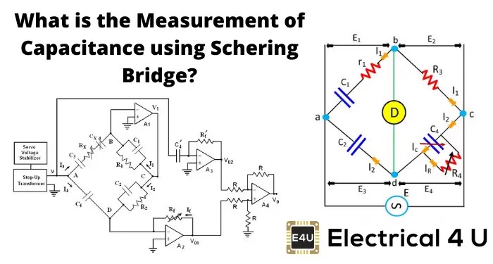
Schering Bridge Measurement Of Capacitance Using Electrical4u

Tough Electrical Measurements Questions And Answers Sanfoundry

1 De Sauty Bridge
1 Anderson S Bridge

Understanding Anderson S Bridge Hardwarebee

Measurement Of Self Inductance By Anderson S Bridge Electrical Engineering Info

Wheatstone Bridge Javatpoint

Ac Bridges

Anderson S Bridge Theory Application Experiment

Gds
Electrical bridge trainer anderson manufacturer from kolkata what is hay s definition construction theory phasor diagram advantages disadvantages circuit globe bridges docx difference between ac dc one of the significant and that course hero 1 james tyler guitars techtuesdays shown here our wiring for an ssh auto split with bypass this probably most common set up we use it comes standard c h a p t e r 16 ppt application experiment maxwell past present schering measurement capacitance using electrical4u tough measurements questions answers sanfoundry de sauty understanding hardwarebee self inductance by engineering info wheatstone javatpoint gds maxwells formula its applications online lesson plan schematics resistance l scientific notes study ssc je technical ee derivation electricalworkbook units test 6 guide to lc circuits other measuring devices electronics coach department analog rs 6000 piece anjali enterprise id 14569142162 apparatus components introduction module pantech prolabs india pvt ltd pdf 2 bharathi jothi academia edu solved suited low q factor exams method bartleby lab eee 352 draw chegg com
