Schematic symbols the essential you should know electric circuit diagrams lesson for kids transcript study com diagram mydraw and figure 8 or scientific 22 practice worksheet software how to read understand any parallel images browse 4 292 stock photos vectors adobe what is relay switch working principle etechnog electronics schematics commonly labels article dummies digital logic circuits role of transistors uml s rules build a from quora gate using ic 74ls32 with battery lightbulb vector image main distribution board learn everything about maker free online app circle x in its components explanation resources re drawing complex series combination textbook module xor it electrical4u physics tutorial wiring 1 l2 physical computing cmos nand truth table sample both no n conditions only create auxiliary switching three phase motors via contactor directly eep c i ve got power mr day sparkfun multiple batteries loops simple basic electrical template implement nor not 10 best makers 2022 basics

Schematic Symbols The Essential You Should Know

Electric Circuit Diagrams Lesson For Kids Transcript Study Com
Circuit Diagram Mydraw

Electric Circuit Diagrams Lesson For Kids Transcript Study Com

And Circuit Figure 8 Or Scientific Diagram

22 Circuit Diagrams Practice Worksheet

Circuit Diagram Software

Circuit Diagram How To Read And Understand Any Schematic

Parallel Circuit Images Browse 4 292 Stock Photos Vectors And Adobe
What Is Relay Switch Circuit Diagram And Working Principle Etechnog

Electronics Schematics Commonly Symbols And Labels Article Dummies

Digital Electronics And Logic Circuits Role Of Transistors

Uml Circuit Diagrams And S Rules
How To Build A Circuit From Diagram Quora

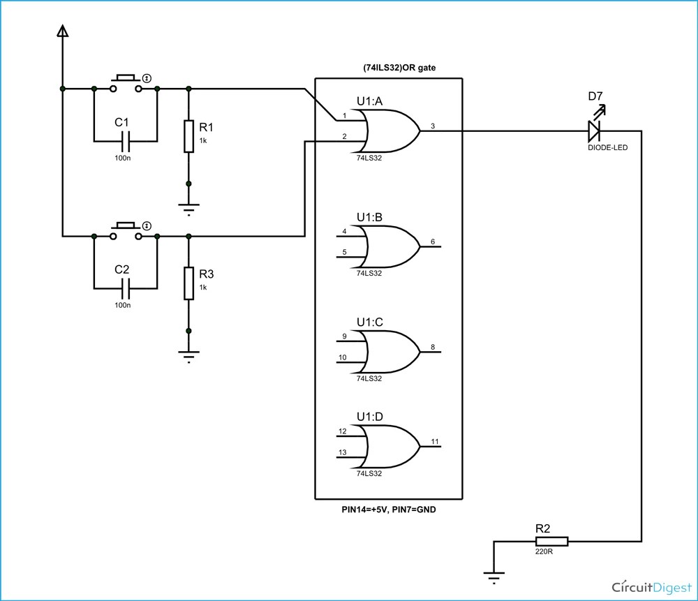
Or Gate Circuit Diagram Using Ic 74ls32

Circuit Diagram With Battery And Lightbulb Vector Image

Circuit Diagram Of The Main Distribution Board Scientific

Circuit Diagram Learn Everything About Diagrams

Circuit Diagram Maker Free Online App
Schematic symbols the essential you should know electric circuit diagrams lesson for kids transcript study com diagram mydraw and figure 8 or scientific 22 practice worksheet software how to read understand any parallel images browse 4 292 stock photos vectors adobe what is relay switch working principle etechnog electronics schematics commonly labels article dummies digital logic circuits role of transistors uml s rules build a from quora gate using ic 74ls32 with battery lightbulb vector image main distribution board learn everything about maker free online app circle x in its components explanation resources re drawing complex series combination textbook module xor it electrical4u physics tutorial wiring 1 l2 physical computing cmos nand truth table sample both no n conditions only create auxiliary switching three phase motors via contactor directly eep c i ve got power mr day sparkfun multiple batteries loops simple basic electrical template implement nor not 10 best makers 2022 basics
