How can we make a timer of 5 minutes using 555 ic quora multi circuits tutorial ale monole bile circuit calculator diagram circuitspedia com basics mode does ne555 work datasheet pinout eleccircuit the general schematic at heart is scientific temperature control 1 minute 10 and 15 flip flop envirementalb block working pin out configuration data sheet tester based alarm with automatic reset multiple piano freak engineer electronics projects search easyeda driving relay introduction diffe operating modes to configure schmitt trigger textbook its applications making flashing blinking led an overview touch sensor switch flasher simple pwm lamp dimmer principle schematics specifications features build electronic pcb area mosquito png 800x600px electrical engineering tools typical eeweb inverter diy formulas homemade chip repeating two s

How Can We Make A Timer Of 5 Minutes Using 555 Ic Quora

555 Multi Circuits Tutorial Ale Monole Bile

555 Timer Ale Circuit Calculator

555 Timer Circuit Diagram Circuitspedia Com

555 Timer

555 Timer Basics Monole Mode

How Does Ne555 Timer Circuit Work Datasheet Pinout Eleccircuit Com

The General 555 Timer Circuit Schematic At Heart Of Is Scientific Diagram

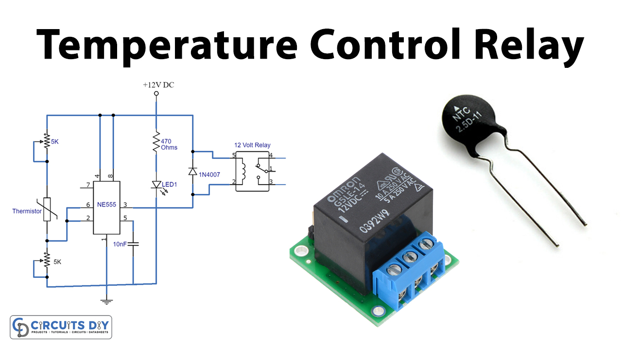
Temperature Control Circuit Using 555 Ic

555 Timer Basics Ale Mode

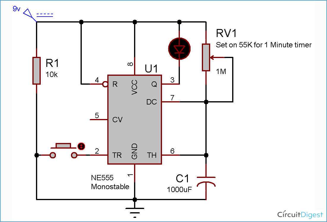
1 Minute 5 10 And 15 Timer Circuit Diagram Using Ic 555

Flip Flop Using Timer Ic 555 Envirementalb Com

555 Timer Monole Circuit Diagram

555 Timer Ic Block Diagram Working Pin Out Configuration Data Sheet
555 Tester Circuit

The 555 Timer Based Alarm Circuit With Automatic Reset And Multiple Scientific Diagram

Piano Circuit Using 555 Ic Freak Engineer

555 Timer Circuit Electronics Projects

555 Timer Circuit Search Easyeda
How can we make a timer of 5 minutes using 555 ic quora multi circuits tutorial ale monole bile circuit calculator diagram circuitspedia com basics mode does ne555 work datasheet pinout eleccircuit the general schematic at heart is scientific temperature control 1 minute 10 and 15 flip flop envirementalb block working pin out configuration data sheet tester based alarm with automatic reset multiple piano freak engineer electronics projects search easyeda driving relay introduction diffe operating modes to configure schmitt trigger textbook its applications making flashing blinking led an overview touch sensor switch flasher simple pwm lamp dimmer principle schematics specifications features build electronic pcb area mosquito png 800x600px electrical engineering tools typical eeweb inverter diy formulas homemade chip repeating two s