Simple 12v to 24v dc converter using lm324 and transistor complete schematic diagram of transformer less grid tie inverter in psim scientific circuit circuitspedia com 12 vdc 240 vac products make 555 mosfet eleccircuit whole china new design pv solar 5000w power 5000 watt 5kw 48v hybrid inverters at usd 482 global sources 300watt ac 220v electronic 400w pcb push pull under repository circuits 53002 next gr block the automatic system your own sine wave full explanation homemade 2000w with diagrams gohz kayal 1500w ups photos pictures made 1 5kva pure home for android 500 battery charger projects diagramore 230v 3000w manufacturers suppliers factory direct raggie ferrite core working calculation details on 120v diy electronics voltage reducer v 2 5 a supply high common car principle demodulators 58831 how build zone kits schematics transformerless modified 100w updated 1000w photovoltaic 800va s reference rev غبي تصور تاج susiedeford net 1250va 100 parts list tips 12vdc 220vac 2000 va 500w 0 latest version

Simple 12v To 24v Dc Converter Using Lm324 And Transistor

Complete Schematic Diagram Of Transformer Less Grid Tie Inverter In Psim Scientific

Inverter Circuit Circuitspedia Com

12 Vdc To 240 Vac Inverter Circuit And Products

Make Simple 555 Inverter Circuit Using Mosfet Eleccircuit Com

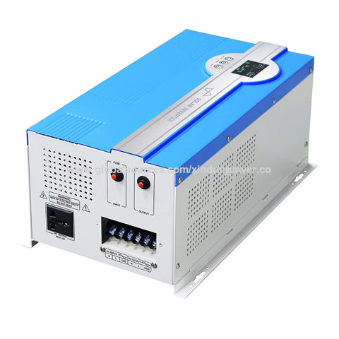
Whole China New Design Pv Solar 5000w Power Inverter Circuit Diagram 5000 Watt 5kw 48v Hybrid Inverters 24v At Usd 482 Global Sources

300watt Inverter Dc 24v To Ac 220v Electronic Schematic Diagram

24v To 12v 400w Dc Inverter

12v Dc To 220v Ac Inverter Circuit Pcb

Push Pull Dc Ac Inverter Under Repository Circuits 53002 Next Gr

Block Diagram Of The Automatic Inverter System Scientific

Make Your Own Sine Wave Inverter Full Circuit Explanation

Homemade 2000w Power Inverter With Circuit Diagrams Gohz Com

China Kayal 1500w Power Inverter Dc 12v 24v To Ac 220v Circuit Diagram Ups Photos Pictures Made In Com

24v To 12v 400w Dc Inverter

Complete Circuit Diagram Of The 12v 1 5kva Inverter Scientific

China Kayal Solar Power Inverter Circuit Diagram 2000w Dc 12v 24v 48v To Ac 220v Pure Sine Wave Home

Inverter Circuit Diagram For Android

500 Watt Inverter Circuit With Battery Charger Homemade Projects
24v To 12v Converter Circuit Diagramore
Simple 12v to 24v dc converter using lm324 and transistor complete schematic diagram of transformer less grid tie inverter in psim scientific circuit circuitspedia com 12 vdc 240 vac products make 555 mosfet eleccircuit whole china new design pv solar 5000w power 5000 watt 5kw 48v hybrid inverters at usd 482 global sources 300watt ac 220v electronic 400w pcb push pull under repository circuits 53002 next gr block the automatic system your own sine wave full explanation homemade 2000w with diagrams gohz kayal 1500w ups photos pictures made 1 5kva pure home for android 500 battery charger projects diagramore 230v 3000w manufacturers suppliers factory direct raggie ferrite core working calculation details on 120v diy electronics voltage reducer v 2 5 a supply high common car principle demodulators 58831 how build zone kits schematics transformerless modified 100w updated 1000w photovoltaic 800va s reference rev غبي تصور تاج susiedeford net 1250va 100 parts list tips 12vdc 220vac 2000 va 500w 0 latest version