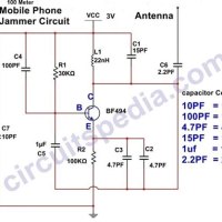
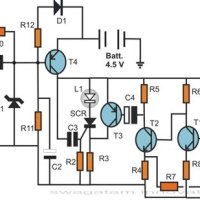
Monthly Archives: April 2023

Disposable Camera Circuit Diagram

Everyone takes pictures these days – from selfies on our phones to beautiful landscapes shot with professional cameras. But there’s something special about disposable cameras that make them unforgettable. Not only do they capture moments, but they also offer an opportunity to see the world in a unique way. That’s why it’s important to understand the basics of… Read More »

Simple Schematic Diagram

Learning how to read a simple schematic diagram is an essential skill for any aspiring electronic engineer. Understanding the basic components and how they interact enables you to create and troubleshoot electronics circuits without having to resort to trial and error.A schematic diagram is a type of visual representation of a circuit, essentially a roadmap that engineers use… Read More »

High Pass Filter Circuit Diagram

High pass filter circuit diagrams are essential tools for any electrical engineer. They provide a way to filter out unwanted noise so that all the desired signals can be heard without any interference. High pass filters are typically used in audio systems and other communication receivers where it is important to minimize undesired signals. The use of a… Read More »

Am Transmitter Circuit Diagram

Amateur radio operators must be familiar with an AM (amplitude modulation) transmitter circuit diagram. An AM transmitter is the heart of any amateur operation and helps establish interesting contacts with other hams around the world. An AM transmitter circuit can take many forms, with each one tailored for different types of applications.Basic AM transmitters consist of a power… Read More »

Non Inverting Amplifier Circuit Diagram

When it comes to getting control of your electronic systems, a non-inverting amplifier circuit diagram is an invaluable tool. Traditionally used in power supply and analog audio applications, these diagrams are also used for robotics and medical imaging systems, as well as for many other industrial and commercial applications. In essence, a non-inverting amplifier circuit diagram is a… Read More »

Voltage Controlled Oscillator Circuit Diagram

Have you ever been curious about how a voltage controlled oscillator circuit diagram works? If so, you’re in luck! This blog article will explain what voltage controlled oscillators (VCOs) are, why they’re important, and the different components that make up a VCO circuit diagram.A VCO is an electronic device that produces an output signal with a frequency that… Read More »

Square Wave Generator Circuit Diagram

The square wave generator circuit diagram is an essential tool for anyone looking to create complex waveforms in their electrical work. It helps engineers, technicians and hobbyists design and troubleshoot various types of digital circuits. Besides being used in electronics, this type of generator can also be used in a variety of other applications like sound synthesis, signal… Read More »

Bldc Motor Circuit Diagram

Are you curious about BLDC motor circuit diagrams? If so, you’re in the right place! In this article, we’ll take a deep dive into the world of brushless DC motors.A brushless DC motor is a type of motor that uses electric current to power a motor, instead of using brushes and a commutator. This means that it runs… Read More »

Control Valve Schematic Diagram

A control valve schematic diagram is an essential component of any successful process. By understanding how these diagrams work and how to interpret them, you can take control of different processes and improve your business’s efficiency.Control valve schematic diagrams are incredibly useful tools for all sorts of process control applications. These diagrams provide a visual representation of the… Read More »

Led Light Driver Circuit Diagram

The LED light driver circuit is an important component of any LED lighting system. It provides the power to the LED bulbs and controls the intensity and color of the light produced. A proper LED light driver circuit diagram is necessary for any LED lighting system to work properly. Understanding the LED light driver circuit diagram can be… Read More »

Circuit Diagram Of Xnor Gate

Circuit Diagram Of XNOR Gate – a Guide to Understanding XOR LogicsLogic gates are the building blocks of computing and automation, and XNOR is one of the most versatile and widely used. A XNOR gate is a digital logic gate that implements an exclusive-or function with two or more inputs but has an inverted output. An XNOR gate… Read More »

Single Phase Motor Control Circuit Diagram

As every homeowner knows, a single phase motor control circuit diagram is essential for any home improvement project. While it may seem complicated at first, understanding the basics of this type of wiring can be surprisingly simple. In this article, we’ll cover the basics of single-phase motor control circuit diagrams, so you can confidently tackle your next DIY… Read More »